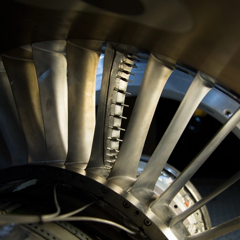
Engineers can design complex machinery for easier assembly and maintenance by applying structured design principles from the earliest stages of development. The core approach combines modular architecture, thoughtful access planning, embedded instrumentation, and simulation-based validation. The sections below address the most common questions engineers face when designing for both buildability and long-term serviceability.
What design principles reduce complexity in large mechanical assemblies?
Reducing complexity in large mechanical assemblies starts with minimising part count, standardising interfaces, and designing components so that their correct orientation is physically obvious. When every part has a clear function and a single correct way to fit, the risk of assembly error drops significantly and maintenance teams spend less time interpreting documentation.
Several principles consistently produce simpler, more reliable assemblies:
- Reduce total part count by combining functions into single components where structurally sound
- Use standard fasteners and connection types across the assembly to reduce tooling requirements
- Design self-locating features so components seat correctly without adjustment
- Avoid symmetrical parts that could be installed backwards or upside down, or make the asymmetry physically impossible to ignore
- Minimise the number of different torque values, clearances, and tolerances that technicians must track
In gas turbine and aerospace engine design, these principles carry particular weight because assembly often takes place in constrained environments, sometimes at customer sites, and errors can have serious downstream consequences. Simplifying the physical logic of an assembly is not just about saving time; it directly affects safety and reliability over the operational life of the machine.
How does modular design improve maintenance access in gas turbines?
Modular design improves maintenance access in gas turbines by grouping components into self-contained units that can be removed, inspected, and replaced independently without disturbing the rest of the engine. This reduces downtime, limits the risk of collateral damage during disassembly, and allows maintenance to be staged or parallelised across teams.
A well-designed modular architecture means that a technician servicing a compressor stage does not need to dismantle the combustion section to reach it. Each module has defined mechanical and fluid interfaces, so the boundaries of any maintenance task are predictable before work begins. This predictability matters enormously in high-value, long-life assets like industrial gas turbines, where unplanned downtime carries significant cost.
Modular thinking also benefits the design process itself. When a system is broken into discrete modules with clear interfaces, engineering teams can develop and validate each module in parallel. Testing becomes more targeted, and design changes to one module are less likely to propagate unexpected consequences into adjacent systems. For manufacturers supporting gas turbine development, this separation of concerns between modules is one of the most effective tools for managing system complexity.
What role does instrumentation play in designing for easier diagnostics?
Instrumentation plays a central role in designing for easier diagnostics by making internal machine states visible without requiring disassembly. When sensors, measurement ports, and data acquisition points are designed into a machine from the start, maintenance teams can identify faults, monitor degradation, and verify performance without taking the system apart.
Designing for diagnostics means deciding early which parameters need to be measurable and then ensuring physical access for the necessary sensors. In a multistage compressor, for example, pressure and temperature taps at each stage boundary allow engineers to isolate where performance has degraded rather than treating the entire compressor as a black box. The same logic applies to vibration monitoring, flow measurement, and thermal imaging access ports.
The challenge is that instrumentation adds mass, potential leak paths, and wiring complexity. Good diagnostic design finds the minimum set of measurement points that provides maximum diagnostic resolution. This requires close collaboration between test engineers and design engineers early in the programme, before access routes are closed off by surrounding structure. Instrumentation decisions made late in a design cycle are almost always more expensive and less effective than those integrated from the start.
How can digital tools and simulation reduce assembly errors before build?
Digital tools and simulation reduce assembly errors before build by allowing engineers to rehearse the entire assembly sequence in a virtual environment, identifying clashes, access constraints, and sequencing problems before any physical parts exist. This virtual validation catches errors that would otherwise only surface during the first physical build, when correction is far more costly.
Modern CAD environments support assembly simulation that checks not just whether parts fit geometrically, but whether they can be physically installed given the tools and human reach required. Finite element analysis can verify that assembly loads and torques do not introduce stress concentrations that would compromise serviceability. Digital twin models can simulate how a machine behaves under operational loads, informing decisions about where wear is likely to occur and where maintenance access should be prioritised.
In aerospace and defence programmes, where first-article builds are expensive and schedules are tight, this kind of front-loaded virtual validation has become standard practice. The investment in simulation time early in the design process consistently reduces rework, shortens build schedules, and produces assemblies that are easier to maintain because the maintenance scenarios were tested digitally before the design was frozen.
What is the difference between design for assembly and design for maintainability?
Design for assembly (DFA) focuses on making a product easier and faster to build correctly the first time, while design for maintainability (DFM) focuses on making it easier to inspect, repair, and service over its operational life. Both disciplines reduce cost and improve reliability, but they optimise for different phases of a product’s lifecycle and sometimes create competing requirements.
Design for assembly
DFA targets the initial build process. Its primary goals are reducing part count, standardising fasteners, minimising assembly steps, and eliminating opportunities for incorrect installation. A design that scores well on DFA criteria can be built quickly and consistently, with low risk of error on the production line or during initial field installation.
Design for maintainability
DFM targets the years of service that follow. Its primary goals are ensuring that worn or failed components can be accessed without excessive disassembly, that replacement parts are interchangeable, that inspection points are reachable, and that maintenance procedures are safe and unambiguous. A design that scores well on DFM criteria keeps maintenance time short and reduces the skill level required for routine servicing.
The tension between these two disciplines is real. A tight, compact assembly that is efficient to build may bury critical components behind others, making maintenance difficult. Conversely, a design with generous maintenance access may require more fasteners or more complex assembly sequences. Resolving this tension requires explicit trade-off decisions, made with input from both assembly engineers and the maintenance teams who will live with the design for its entire service life.
When should maintainability requirements be introduced into the design process?
Maintainability requirements should be introduced at the very beginning of the design process, during the concept and requirements definition phase. Introducing them later, once the basic architecture is established, means working around decisions that were made without maintenance in mind, which almost always produces a less effective outcome and costs more to correct.
The practical reason for early introduction is that the most consequential maintainability decisions are architectural. Where a module boundary sits, how two major assemblies interface, whether a housing splits horizontally or vertically: these choices determine maintenance access for the life of the product. Once they are made and surrounding structure is designed around them, changing them is expensive.
In practice, maintainability requirements are often introduced too late because the teams responsible for maintenance are not involved in early design reviews. Bridging this gap requires deliberate programme management: maintenance engineers should review concept designs, contribute to access studies, and sign off on interface definitions before detailed design begins. For complex systems like aero engines or industrial gas turbines, some programmes use formal maintainability analysis methods to quantify the time and skill required for each maintenance task, then feed that data back into design decisions while changes are still straightforward to make.
How AneCom supports design for assembly and maintainability
AneCom AeroTest provides engineering services that directly address the challenges described throughout this article. As a specialist in aero engine and gas turbine development, the company supports design teams at the point where design intent meets physical reality, during instrumentation, assembly, and experimental testing.
- Instrumentation design and integration, ensuring measurement points are built into test vehicles from the start rather than retrofitted
- Assembly of complex test articles, drawing on hands-on experience with multistage compressors, combustion chambers, and turbine components
- Aerothermal component testing that generates validation data used to inform design decisions before production commitments are made
- Non-destructive testing services that support maintainability by identifying component condition without disassembly
- Engineering support at customer sites worldwide, providing design-for-assembly expertise where and when it is needed
If your programme needs engineering support across design, instrumentation, assembly, or testing of complex aero engine or gas turbine components, get in touch with AneCom to discuss your requirements.