Design for maintainability (DfM) is a mechanical engineering discipline that shapes how a system is designed so it can be inspected, serviced, repaired, and kept operational throughout its working life with minimum time, cost, and effort. It treats maintenance not as an afterthought but as a design constraint, placing serviceability requirements alongside performance and structural ones from the earliest stages of development. The sections below address the most common questions engineers and procurement teams ask when applying maintainability thinking to complex mechanical systems.
What principles guide design for maintainability decisions?
Design for maintainability is guided by a set of engineering principles that prioritize access, standardization, modularity, and fault visibility. The core idea is that every design choice affecting how a component is reached, identified, removed, or replaced should be made deliberately, with the maintenance technician’s workflow in mind rather than purely around manufacturing or performance constraints.
Accessibility is the most immediate concern. Components that require frequent attention should be reachable without removing unrelated parts. This shapes decisions about fastener placement, panel locations, and the sequencing of assemblies. Where access is physically constrained, designers look for ways to extend service intervals so that difficult-to-reach components need attention less often.
Standardization reduces the variety of tools, skills, and spare parts a maintenance team must carry. When fasteners, seals, and connectors are standardized across a system, technicians work faster and with fewer errors. Modularity extends this principle by grouping components into replaceable units that can be swapped without disturbing the surrounding system, reducing downtime even when a root cause has not yet been fully diagnosed.
Fault visibility, sometimes called testability, is the principle that a system should make its own condition legible. This means designing in diagnostic access points, clear wear indicators, and logical failure modes that point toward the affected subsystem rather than obscuring it.
How does design for maintainability differ from reliability engineering?
Reliability engineering focuses on preventing failure, while design for maintainability focuses on what happens after failure occurs or when scheduled maintenance is due. Both disciplines contribute to system availability, but they address different parts of the availability equation and require different design interventions.
A reliability engineer works to extend mean time between failures (MTBF) by selecting materials with appropriate fatigue life, specifying tighter tolerances, and reducing stress concentrations. The goal is to make the system fail less often. A maintainability engineer, by contrast, works to reduce mean time to repair (MTTR) by making the system easier to work on when maintenance is needed, whether that maintenance is corrective or preventive.
In practice, the two disciplines interact and sometimes create tension. A highly reliable component might be sealed, potted, or integrated in ways that make it difficult to inspect or replace. A highly maintainable design might use modular assemblies that introduce additional interfaces, each of which is a potential failure point. Experienced engineering teams treat reliability and maintainability as complementary constraints to be balanced rather than competing priorities where one dominates.
What are the key metrics used to measure maintainability?
The primary metric for maintainability is mean time to repair (MTTR), which measures the average time required to restore a system to operational condition after a failure. Alongside MTTR, engineers track mean time between maintenance actions (MTBMA), which accounts for both corrective and preventive maintenance events, and maintenance man-hours per flight hour (MMH/FH) in aerospace applications.
These metrics are not independent. A system with a low MTTR but very frequent maintenance actions may still impose a high maintenance burden. The combination of MTBMA and MTTR together determines maintenance labor demand, which directly affects operational costs and workforce planning.
Other measurable indicators include the fraction of maintenance tasks completable without special tooling, the number of task steps required for common maintenance actions, and the time required to isolate a fault to a replaceable unit. These more granular measures are useful during design reviews because they can be estimated from drawings and task analyses before a physical prototype exists, allowing teams to compare design options before committing to a configuration.
How is design for maintainability applied in aero engine development?
In aero engine development, design for maintainability is applied across every major module, including the fan, compressor, combustor, and turbine, with particular attention to the components that experience the highest thermal and mechanical loads and therefore require the most frequent inspection.
Borescope access is one of the most consequential maintainability decisions in engine design. Borescope ports allow technicians to inspect internal surfaces, blades, and seals without disassembling the engine, which can save many hours of ground time per inspection cycle. The placement and quantity of these ports are determined during the preliminary design phase, when the engine’s internal geometry is still flexible enough to accommodate them without compromising aerodynamic performance.
Line-replaceable units (LRUs) are another central concept. Designers group components by their expected service life and failure behavior, then package them so that the shorter-lived items can be replaced at line maintenance without removing the entire module. This is particularly relevant for accessories, fuel system components, and sensors, where replacement frequency is higher than for the core structure.
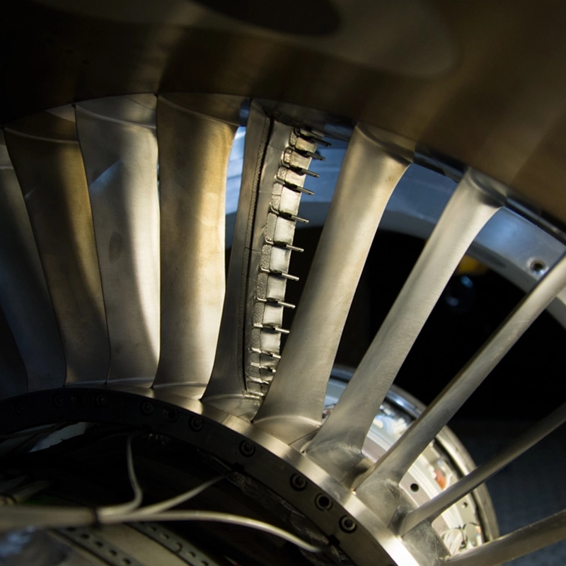
Testing plays a direct role in validating maintainability assumptions. During component and system testing, teams measure actual task times, identify unforeseen access constraints, and assess whether fault isolation procedures work as designed. Data gathered during aerothermal component testing, for example, can reveal thermal gradients that affect how seals and coatings degrade, which in turn informs decisions about inspection intervals and the design of wear indicators.
When should maintainability requirements be defined in the design process?
Maintainability requirements should be defined at the concept phase, before major architecture decisions have been made. The earlier maintainability targets are established, the more design freedom exists to meet them without significant cost or weight penalties.
When maintainability is addressed late in the design process, the available interventions are limited to minor adjustments: repositioning a fastener, adding a label, or revising a maintenance procedure. These changes can improve the situation at the margins but cannot correct a fundamental architecture that places a high-wear component behind several others that must be removed first.
In practice, maintainability requirements are often captured in a maintenance concept document that is developed alongside the system requirements at program inception. This document defines the intended maintenance levels (on-wing, line, base, or depot), the maximum acceptable task times for critical maintenance actions, and the tooling and skill constraints that apply to the intended operating environment. These parameters then flow down into design specifications for individual subsystems and components.
Design reviews at the preliminary and critical design stages should include explicit maintainability assessments, comparing the current design against the maintenance concept targets and identifying any gaps while changes are still practical.
What tools and methods support maintainability analysis during design?
Maintainability analysis during design relies on a combination of task analysis methods, simulation tools, and formal assessment frameworks. The most widely used formal method is maintainability prediction, which estimates MTTR and maintenance man-hours based on task inventories derived from the design documentation.
Maintenance task analysis (MTA) breaks down each anticipated maintenance action into discrete steps, assigns time estimates to each step, and identifies the tools, access conditions, and personnel qualifications required. This produces a structured record that can be reviewed against the maintenance concept targets and used to identify tasks that exceed acceptable time limits.
Digital human modeling and virtual reality environments allow engineers to simulate maintenance tasks in a three-dimensional representation of the design before hardware exists. A technician avatar can be positioned at the work site to check whether reach, line of sight, and clearance are adequate for the required task. This is particularly useful for identifying access problems in densely packaged assemblies where two-dimensional drawings are insufficient to reveal spatial conflicts.
Failure mode and effects analysis (FMEA) contributes to maintainability by identifying the failure modes that are most likely to occur and assessing whether the design allows those failures to be detected, isolated, and corrected efficiently. When an FMEA reveals a failure mode that would be difficult to diagnose or repair, that finding feeds back into the design as a requirement to improve fault visibility or reconfigure the affected assembly.
For gas turbine applications, these methods are often supplemented by data from component testing, which provides empirical evidence about degradation rates, failure locations, and the condition of parts after service exposure. Test data of this kind allow maintainability predictions to be validated and refined rather than relying entirely on analytical estimates.
How AneCom supports maintainability-driven aero engine design
AneCom AeroTest provides engineering and testing services that directly support the maintainability objectives of aero engine and gas turbine development programs. Working across the full range of aerothermal components, the team can help design and validation teams gather the test data they need to make informed maintainability decisions early in the program.
- Aerothermal component testing for compressors, combustors, and turbine parts, generating empirical data on degradation behavior and component life that informs inspection interval decisions
- Instrumentation and assembly services that support the integration of diagnostic access points and sensor systems into test vehicles
- Non-destructive testing services for turbine blades and other high-value components, providing inspection data that validates condition-based maintenance approaches
- Fan system acoustic testing in Europe’s largest anechoic chamber, supporting the validation of fan designs that must meet both performance and serviceability targets
- Engineering analysis services, including design and analysis work that can be applied to maintainability assessments and task analysis support
If your program needs test data or engineering support to validate maintainability assumptions at the component or system level, contact the AneCom team to discuss how the facilities and expertise at Wildau can be applied to your development requirements.