Design for manufacture (DFM) is a mechanical engineering methodology that shapes a product’s design to make it easier, faster, and less costly to produce. Rather than treating manufacturing as a downstream concern, DFM integrates production considerations directly into the design phase, so the geometry, materials, and tolerances of a component are chosen with the manufacturing process in mind from the outset. The sections below address the most common questions engineers and procurement teams have about how DFM works and where it adds the most value.
How does design for manufacture actually work in practice?
Design for manufacture works by evaluating design decisions against the capabilities and constraints of the intended manufacturing process before production begins. Engineers review geometry, material selection, tolerances, and surface finish requirements in parallel with design development, identifying features that would be difficult or costly to produce and modifying them early, when changes are still inexpensive.
In practice, DFM typically involves collaboration between design engineers and manufacturing engineers at defined review points in the development cycle. A part might be redesigned to eliminate undercuts that complicate moulding, to standardise fastener sizes across an assembly, or to relax a tolerance that was tighter than the function actually required. The goal is not to compromise performance but to achieve equivalent performance through geometry and process choices that are easier to execute reliably at scale.
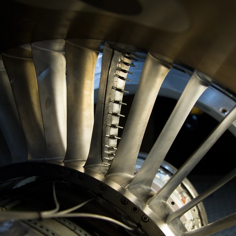
For complex components such as compressor blades or turbine casings, DFM reviews often include simulation of the manufacturing process itself, checking whether a machining path is achievable, whether a casting will fill correctly, or whether a weld joint can be accessed by standard tooling. This kind of analysis turns manufacturing knowledge into a design input rather than a late-stage constraint.
What are the core principles of design for manufacture?
The core principles of design for manufacture are simplicity, standardisation, and process alignment. Simplicity means reducing part count and geometric complexity wherever function allows. Standardisation means using common materials, fasteners, and features that existing tooling and processes can handle. Process alignment means selecting geometries and tolerances that suit the specific manufacturing method being used, whether that is machining, casting, forming, or additive manufacturing.
Beyond these three foundations, DFM also emphasises designing for inspection and quality control. A component that is difficult to measure is a component that is difficult to accept or reject with confidence, which introduces risk into the supply chain. Features should be positioned and dimensioned so that standard gauging and metrology equipment can verify them without custom fixturing.
Material selection is another area where DFM principles apply directly. Choosing a material that machines predictably, holds tolerances well, and is available in standard stock sizes reduces lead time and scrap rates compared with specifying an exotic alloy that requires specialist processing, even if the exotic alloy offers marginal performance benefits that the application does not strictly need.
What is the difference between DFM and DFA?
DFM (design for manufacture) focuses on how individual parts are made, while DFA (design for assembly) focuses on how parts are joined together to form a complete product. DFM asks whether a single component can be produced efficiently; DFA asks whether the resulting components can be assembled quickly, with few tools, and with low risk of error. The two disciplines are related but address different stages and different cost drivers.
In many engineering organisations, DFM and DFA are combined under the umbrella of DFMA (design for manufacture and assembly), because decisions made for one often affect the other. Reducing part count through DFA, for example, simplifies assembly but may increase the geometric complexity of individual parts, which has direct implications for DFM. Effective product design balances both sets of considerations together rather than optimising one at the expense of the other.
For aerospace and gas turbine components, where assembly sequences are tightly controlled and access is often restricted, DFA considerations can be as significant as DFM. A component that is straightforward to machine but requires a non-standard tool to install in the engine adds cost and risk at the assembly stage that offsets the manufacturing saving.
When should DFM analysis be applied in the engineering process?
DFM analysis should be applied as early as the conceptual design phase, and revisited at each major design review through to detailed design. The earlier DFM is integrated, the lower the cost of any changes it identifies. Modifications made during concept development cost a fraction of what the same change would cost after tooling has been ordered or prototypes have been built.
The conventional engineering advice holds that roughly 70 to 80 percent of a product’s manufacturing cost is determined during the design phase, before a single part has been made. This reflects the fact that design decisions lock in material choices, process routes, tolerance requirements, and part counts, all of which drive cost. Waiting until design is complete to consider manufacturability means accepting most of that cost as fixed.
In practice, DFM should be a recurring activity rather than a one-time gate. As a design evolves and new information becomes available about supplier capabilities, material availability, or production volumes, the manufacturability picture changes. Formal DFM reviews at concept, preliminary design, and detailed design stages, supported by informal consultation between design and manufacturing teams throughout, give the best results.
Which manufacturing processes benefit most from DFM?
All manufacturing processes benefit from DFM, but the methodology has the greatest impact on processes with high tooling costs, tight tolerance requirements, or complex setup procedures. Injection moulding, die casting, precision machining, and additive manufacturing are the processes where DFM analysis most consistently produces measurable cost and quality improvements.
For injection moulding and die casting, DFM identifies issues such as undercuts, insufficient draft angles, wall thickness variations that cause sink marks, and gate locations that create weld lines in structurally sensitive areas. These are problems that are expensive to correct after tooling is cut, so catching them in design is where the value lies.
For precision machining, which is central to aerospace component production, DFM analysis examines whether features can be reached by standard cutting tools, whether fixturing is straightforward, and whether tolerances are specified at levels that the process can hold consistently. Unnecessarily tight tolerances on non-critical features drive up cycle time and scrap rates without contributing to function.
Additive manufacturing presents a different set of DFM considerations, including support structure requirements, build orientation, and the relationship between layer thickness and surface finish. As additive processes become more common in gas turbine and mechanical engineering applications, DFM frameworks are evolving to address them specifically.
How does DFM reduce cost and production risk in aerospace components?
DFM reduces cost in aerospace component production by eliminating unnecessary complexity before it becomes embedded in tooling, process plans, and supplier contracts. It reduces production risk by ensuring that components are designed to tolerances and geometries that the manufacturing process can achieve reliably, rather than at the edge of process capability where variation causes scrap and rework.
Aerospace components operate under demanding conditions and are subject to rigorous certification requirements, which means that design changes after certification are costly and time-consuming. Getting the design right for manufacture before certification is therefore not just a cost issue but a schedule and compliance issue. DFM analysis during development reduces the probability that a manufacturing-driven design change will be needed after the certification baseline has been established.
For gas turbine components in particular, where materials such as nickel superalloys and titanium alloys are expensive and difficult to machine, DFM has a direct effect on material yield and machining time. A design that minimises material removal, uses standard stock sizes, and avoids features that require specialist tooling can reduce component cost substantially without any change to functional performance.
How AneCom supports DFM-driven component development
AneCom AeroTest brings together design, instrumentation, and testing capabilities that directly support DFM-informed development of aero-engine and gas turbine components. For engineering teams working through the manufacturability of complex aerothermal parts, AneCom offers:
- Design and analysis services that integrate manufacturing constraints from the earliest stages of component development
- Experimental validation testing for compressors, combustors, and turbine components, providing the performance data needed to confirm that DFM-driven design changes have not compromised aerothermal function
- Instrumentation and assembly expertise that reflects real-world production and test requirements, helping teams identify features that create difficulty in both manufacture and integration
- Non-destructive testing services that support quality verification of components produced to DFM-optimised designs
For teams developing components where engineering and testing services need to work in parallel with design decisions, AneCom provides the infrastructure and expertise to make that integration practical. To discuss how AneCom can support your component development programme, get in touch with the team.