
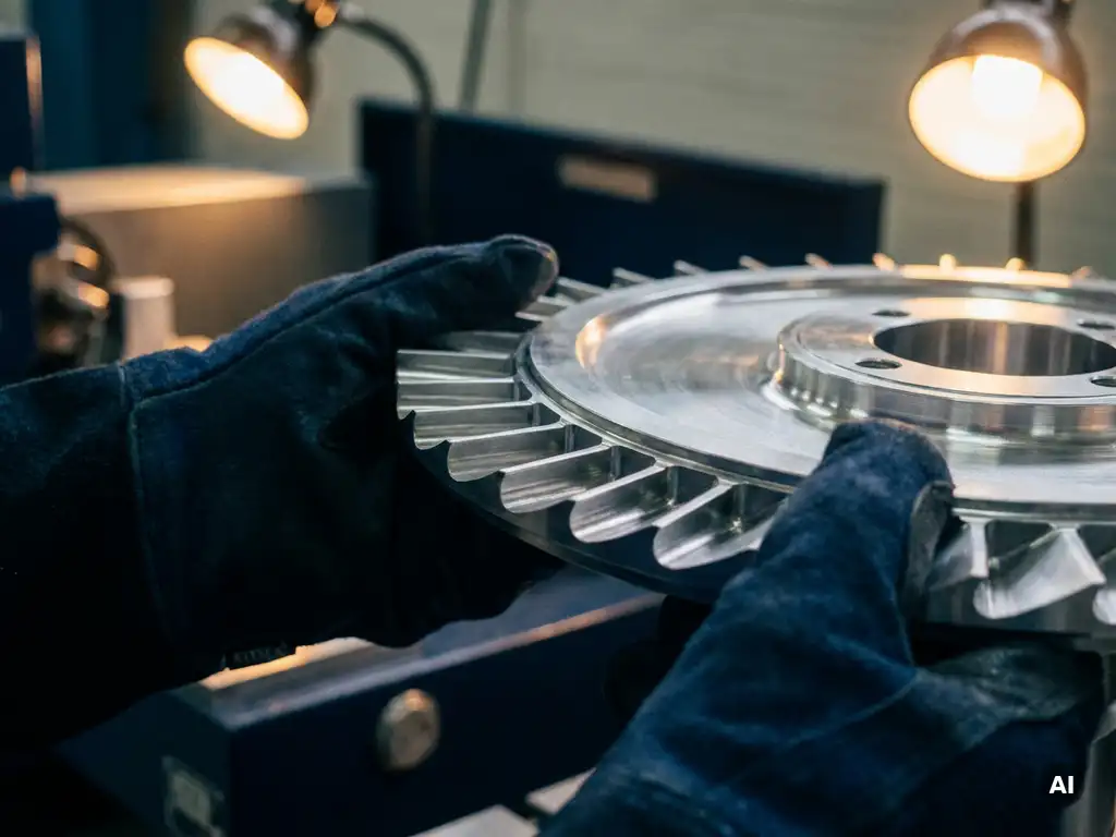
Tolerance management is important in rotating assemblies because even small dimensional errors accumulate across multiple components, directly affecting clearances, load distribution, and dynamic balance. In gas turbines and aero engines, where parts spin at thousands of revolutions per minute under extreme thermal and mechanical loads, the margin between acceptable performance and mechanical failure is extremely narrow. The sections below address the most common technical questions engineers face when working with tolerance-controlled rotating systems.
What happens when tolerances are exceeded in a rotating assembly?
When tolerances are exceeded in a rotating assembly, the result is misalignment, uneven load distribution, or inadequate clearance between moving parts. In practice, this can cause accelerated wear, vibration, blade-tip rubs, or, in severe cases, structural failure. Even a deviation of a few micrometres at a critical interface can propagate into a performance or safety problem once the assembly is running at operating speed.
In aero engine compressors, tight clearances between blade tips and the casing wall are maintained to maximize aerodynamic efficiency. If those clearances grow beyond specification due to a dimensional error during assembly, the pressure ratio drops and fuel consumption rises. If the clearance is too tight, contact between rotating and static components becomes likely, particularly during thermal transients when differential expansion rates are highest. Both scenarios carry significant operational consequences.
Tolerance exceedances also affect rotor balance. A shaft assembly that deviates from its nominal geometry introduces mass eccentricity, which generates centrifugal forces that grow with the square of rotational speed. At the speeds typical of gas turbine operation, even small imbalances translate into large dynamic loads on bearings and housings.
What is stack-up analysis and how does it apply to rotating assemblies?
Stack-up analysis is a method for calculating how individual dimensional tolerances accumulate across a series of mating components to determine the total variation at a critical interface. In rotating assemblies, it applies wherever multiple parts are assembled in sequence, since the tolerance of each part contributes to the final gap, fit, or alignment condition at the assembly level.
There are two primary approaches. Worst-case stack-up assumes every component is at the extreme end of its tolerance simultaneously, which gives a conservative bound but can result in overly tight individual tolerances that are expensive to manufacture. Statistical stack-up, typically using root-sum-square methods, assumes that individual part dimensions follow a distribution and that extreme combinations are unlikely. This approach is more realistic for high-volume production but requires a clear understanding of the manufacturing process capability at each step.
For rotating assemblies in particular, stack-up analysis must account for the fact that tolerances interact in three dimensions. Axial, radial, and angular deviations all contribute to the final assembly condition. In a multistage compressor, for example, the cumulative effect of stage-to-stage axial positioning errors determines rotor axial location relative to the stator, which directly affects the aerodynamic matching between blade rows.
How do operating conditions affect dimensional tolerances in aero engines?
Operating conditions in aero engines cause components to expand, contract, and deflect in ways that change effective clearances and fits during operation. The dimensional tolerances specified at assembly represent a cold, static condition, but the actual functional clearances are determined by how each material responds to temperature, pressure, and centrifugal loading during a real operating cycle.
Thermal expansion is the dominant factor. Different materials used in a single assembly, such as titanium compressor discs paired with nickel-alloy casings, have different coefficients of thermal expansion. As temperatures rise during engine operation, these materials grow at different rates, changing the clearance at blade tips, the interference at disc-to-shaft fits, and the contact pressure at flanged joints. Tolerance specifications must account for these differential growth rates so that the assembly remains within acceptable limits across the full operating envelope.
Centrifugal loading adds another layer of complexity. Rotating discs and blades deform radially under centrifugal force, which effectively reduces tip clearances as speed increases. This effect is predictable through structural analysis, but it must be incorporated into the tolerance budget from the start of the design phase. Pressure loads on casings and bearing housings also contribute to dimensional changes that affect how tightly mating surfaces remain in contact.
What are the most critical tolerance-controlled interfaces in a gas turbine compressor?
The most critical tolerance-controlled interfaces in a gas turbine compressor are blade tip clearances, disc-to-shaft fits, and flange-to-flange axial joints. Each of these directly affects either aerodynamic performance, structural integrity, or rotor-dynamic behaviour, and each is sensitive to dimensional variation in ways that are difficult to correct after assembly.
Blade tip clearance is often treated as the single most performance-sensitive dimension in a compressor. The gap between the rotating blade tip and the stationary casing wall must be large enough to prevent contact under all operating conditions, but small enough to limit the aerodynamic leakage that reduces stage efficiency. Managing this clearance requires coordinated control of blade length, disc bore, shaft diameter, and casing inner diameter.
Disc-to-shaft fits, typically interference fits, must be tight enough to transmit torque without slip but not so tight that assembly becomes impractical or that hoop stresses in the disc exceed material limits. The tolerance window for these fits is narrow, and it shrinks further when thermal and centrifugal growth during operation are factored in.
Flange joints between compressor stages control the axial positioning of each rotor stage relative to its corresponding stator. Errors here affect the incidence angle of flow onto the downstream blade row, which changes the aerodynamic loading and can shift the compressor’s surge margin. For engineers working on aerospace compressor development, maintaining tight control over these interfaces is a core part of the design and assembly process.
How is tolerance management validated through component testing?
Tolerance management is validated through component testing by measuring actual assembly dimensions against design intent and then comparing aerodynamic, structural, and dynamic performance against predictions. Testing reveals whether the tolerance decisions made during design produce the intended functional outcome when real parts are assembled under real conditions.
Dimensional inspection after assembly, using coordinate measuring machines and optical measurement systems, confirms that individual interfaces are within specification before the assembly enters a test rig. This step catches manufacturing deviations early and prevents a known out-of-tolerance condition from contaminating test data.
During rig testing, performance measurements provide indirect evidence that tolerance-controlled interfaces are functioning as designed. A compressor that meets its pressure ratio and efficiency targets across its operating range is behaving consistently with its aerodynamic design, which in turn confirms that the critical clearances and alignments are within the intended range. Rotor vibration signatures during testing also reveal whether the assembled rotor balance and bearing fits are within acceptable limits.
Where testing reveals a discrepancy between predicted and measured performance, engineers can use the dimensional inspection records to determine whether a tolerance deviation is the likely cause. This feedback loop between dimensional data and performance data is what makes structured tolerance management a practical tool rather than a purely theoretical exercise. AneCom’s testing and engineering services are structured to support exactly this kind of data-driven validation across compressor and aerothermal components.
What tools and methods are used to control tolerances during assembly?
Tolerance control during assembly relies on a combination of precision measurement tools, selective assembly techniques, and defined assembly procedures. The goal is to ensure that the dimensional relationships between mating parts fall within the specified range, even when individual components are at different points within their individual tolerance bands.
Coordinate measuring machines provide three-dimensional dimensional data on machined surfaces and are used both for incoming inspection of individual parts and for verification of subassemblies. For rotating components, dedicated roundness and runout measurement equipment captures the geometric form of shafts, bores, and flanges, which is particularly relevant for rotor balance and bearing fit assessment.
Selective assembly is a practical method for managing tight clearances without requiring extremely tight individual part tolerances. Parts are measured and sorted into dimensional groups, and components from matching groups are paired during assembly. This approach is common for blade tip clearance management in compressor assemblies, where pairing blades and discs from complementary measurement bands can achieve a tighter effective clearance than would be possible through random selection.
Process documentation and assembly sequencing also play a role. Defined torque values for fasteners, controlled temperature conditions during interference-fit assembly, and step-by-step verification checks at each stage of build all reduce the chance that a tolerance-compliant set of individual parts produces an out-of-tolerance assembly. For gas turbine assembly work in particular, these procedural controls are as important as the measurement tools themselves.
How AneCom supports tolerance management in rotating assemblies
AneCom AeroTest provides engineering and testing services specifically designed to support tolerance management across the full development cycle of aero engine and gas turbine components. For teams working on compressor and aerothermal component development, AneCom offers:
- Instrumentation and assembly services for complex rotating test vehicles, with dimensional verification built into the assembly process
- Experimental testing of multistage compressor systems on dedicated test benches, generating performance data that validates whether tolerance decisions translate into the intended aerodynamic and structural behaviour
- Design and analysis support, including assessment of stack-up conditions and operating-condition effects on critical interfaces
- Non-destructive testing services for component inspection, relevant to identifying dimensional or structural deviations before and after test campaigns
If your development programme involves rotating assemblies where dimensional control is a limiting factor in performance or reliability, contact AneCom to discuss how testing and engineering support can be structured around your specific tolerance management requirements.
Related Articles
- What is the difference between a prototype and a proof of concept?
- What should be checked before a mechanical design is released for manufacturing?
- What are the limitations of using a Pugh matrix for engineering decisions?
- What should engineers consider when designing rotating components?
- How can conflicting engineering requirements be handled during concept selection?