
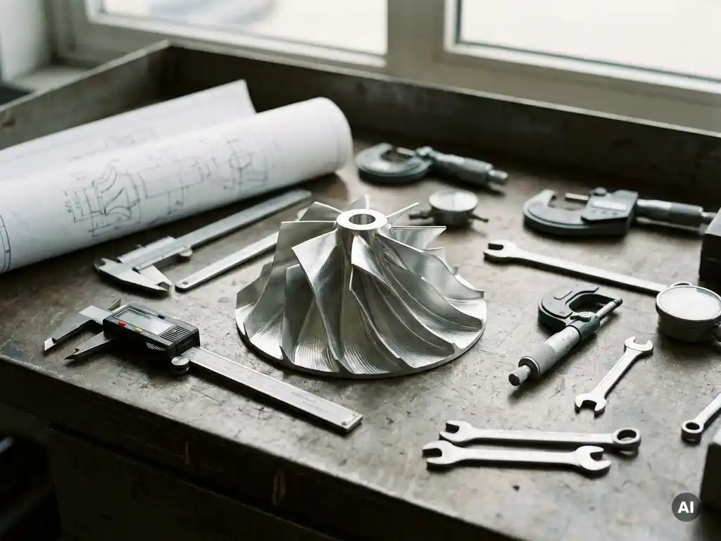
Engineers turn requirements into a mechanical prototype by following a structured process: translating specifications into design concepts, validating those concepts through analysis and simulation, selecting appropriate manufacturing methods, and then building and instrumenting a physical unit for testing. The process is iterative rather than linear, with each stage informing the next. The sections below address the most common questions engineers encounter along the way.
What steps convert engineering requirements into a design concept?
Converting engineering requirements into a design concept begins with decomposing high-level specifications into measurable, physical constraints. Engineers extract performance targets, geometric boundaries, material limits, and interface conditions from the requirements document, then generate candidate architectures that satisfy those constraints simultaneously. The output is a set of ranked concepts ready for analysis.
The first task is to separate functional requirements from constraints. A functional requirement describes what the design must do, for example deliver a specific mass flow rate or withstand a defined pressure ratio. A constraint describes what it must not violate, such as an envelope dimension or a maximum operating temperature. Keeping these categories distinct prevents designers from optimising the wrong variables early in the process.
Once requirements are categorised, engineering teams use tools such as function trees, morphological charts, and trade studies to generate and compare concept options. Each candidate is scored against weighted criteria drawn directly from the requirements. The concept with the highest weighted score moves forward, though teams often carry two or three concepts into the next phase to preserve flexibility before committing to a single direction.
How do engineers validate a design before building anything physical?
Engineers validate a design before physical construction primarily through computational analysis and simulation. Finite element analysis checks structural integrity under expected loads, computational fluid dynamics models aerodynamic or thermal behaviour, and kinematic simulations verify motion and clearances. Together, these tools expose design weaknesses at a fraction of the cost and time of physical testing.
Analytical validation typically runs in parallel with design iteration. As geometry changes, simulation models are updated and re-run, creating a feedback loop that progressively narrows the gap between predicted and required performance. The goal at this stage is not to achieve perfection but to identify any fundamental flaw, whether a resonant frequency that falls within the operating range, a stress concentration that exceeds material limits, or a flow separation that degrades efficiency.
Design reviews provide a second layer of validation. Structured reviews bring together engineers from different disciplines, including stress, aerodynamics, manufacturing, and instrumentation, to challenge assumptions and check that requirements are still being met as the design evolves. A design that survives both computational analysis and a rigorous review process carries significantly lower risk into the prototype build phase.
What is the difference between a proof-of-concept and an engineering prototype?
A proof-of-concept demonstrates that a core physical principle works under controlled conditions. An engineering prototype is a more complete physical realisation of the intended design, built to representative geometry and materials, and used to measure performance against actual requirements. The two serve different purposes and are rarely interchangeable.
Proof-of-concept builds are typically simple, inexpensive, and deliberately incomplete. They answer a binary question: does the underlying mechanism function at all? An engineering prototype, by contrast, must be representative enough to generate data that predicts how the production design will behave. This means tighter dimensional tolerances, correct material properties, and integrated instrumentation.
In practice, many development programmes skip the proof-of-concept stage when the underlying physics are already well understood, moving directly to an engineering prototype. In high-risk or novel technology programmes, particularly in aerospace development, both stages are used in sequence to manage technical risk before committing to expensive full-scale hardware.
Which manufacturing methods are used to build mechanical prototypes?
The manufacturing methods used for mechanical prototypes depend on the required fidelity, material, and timeline. Common approaches include CNC machining for metal components that need tight tolerances, additive manufacturing for complex geometries or rapid iteration, and sheet metal fabrication for structural enclosures and housings. The choice directly affects how representative the prototype is of the final design.
CNC machining remains the standard for aerothermal and rotating components where dimensional accuracy and surface finish directly influence measured performance. Additive manufacturing, including selective laser melting for metals, has expanded the range of geometries that can be prototyped quickly, though engineers must account for differences in material microstructure and surface roughness compared to wrought or cast production parts.
For assemblies that combine multiple manufacturing processes, the sequencing of operations matters as much as the individual methods. Welding, heat treatment, and surface coating each introduce dimensional changes that must be anticipated and compensated for in the machining plan. Prototype build drawings therefore include not just final dimensions but the full manufacturing sequence, so that each operation can be verified before the next begins.
How is instrumentation integrated into a mechanical prototype for testing?
Instrumentation is integrated into a mechanical prototype by designing measurement access into the hardware from the start. Pressure taps, thermocouple ports, strain gauge bridges, and optical access windows must be planned during the design phase, not added as afterthoughts. Late instrumentation changes often compromise structural integrity or introduce flow disturbances that corrupt the data being collected.
The instrumentation plan begins with a list of the physical quantities that must be measured to validate the design against its requirements. From that list, engineers select sensor types, determine locations that give representative readings without disturbing the flow or load path, and specify the signal conditioning and data acquisition hardware needed to capture and process the signals at the required sample rates.
Routing signal cables and pressure lines through a prototype without introducing leaks, electrical interference, or mechanical stress on the sensors is a detailed engineering task in itself. In rotating assemblies, telemetry systems or slip rings are required to transmit signals from instrumented blades or shafts to stationary data acquisition equipment. The integrity of the instrumentation chain is as important as the design being tested: a poorly installed sensor produces data that cannot be trusted, regardless of how well the hardware performs.
What happens when prototype test data does not match predictions?
When prototype test data does not match predictions, the engineering team investigates whether the discrepancy originates in the design, the simulation model, the instrumentation, or the test conditions. Each source requires a different corrective action. The investigation is structured and methodical, working through potential causes in order of likelihood before any hardware changes are made.
The first step is to verify the test setup. Incorrect boundary conditions, leaks in the pressure system, sensor miscalibration, or data acquisition errors can all produce apparent discrepancies that disappear once the test is run correctly. Eliminating measurement error before questioning the design saves significant time and prevents unnecessary hardware modifications.
If the test setup is confirmed to be correct, attention turns to the simulation model. Boundary conditions, turbulence models, and material property assumptions all influence predicted results. Updating the model to reflect what was actually measured during the test, a process called model correlation, produces a more accurate tool for predicting the next design iteration. In some cases, the test data reveals a physical phenomenon that the model did not capture at all, which becomes a finding in its own right and informs future development work across similar programmes.
How AneCom supports the prototype development process
AneCom AeroTest provides engineering teams with the test infrastructure and specialist expertise needed to close the gap between design predictions and measured performance. For organisations developing compressors, fans, combustors, or turbine components, AneCom offers the following:
- Aerothermal component testing on dedicated test benches, covering multistage compressor systems and aero-engine fans with high-fidelity instrumentation
- Acoustic validation in Europe’s largest anechoic chamber, where fan noise measurements are taken under free-field conditions without weather or environmental interference
- Instrumentation design and installation, including sensor selection, signal routing, and data acquisition system integration for complex rotating hardware
- Engineering analysis and design review services, supporting teams from requirements definition through to post-test model correlation
- Non-destructive testing and inspection of prototype hardware, identifying material or manufacturing anomalies before they affect test results
AneCom works with gas turbine OEMs, defence programmes, and research organisations across the full range of test and engineering services, operating from its facility at the Aerospace Technology Centre in Wildau near Berlin and at customer sites worldwide. If your programme needs independent test capability or engineering support at any stage of the prototype development process, contact the AneCom team to discuss your requirements.
Related Articles
- What is the difference between a prototype and a proof of concept?
- How many design concepts should engineers evaluate before selecting one?
- What should engineers consider when designing rotating components?
- Why are tolerances important on mechanical engineering drawings?
- When should engineers use a decision matrix instead of engineering judgement?