
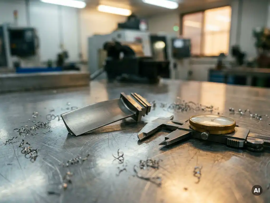
Design for manufacture (DFM) is a mechanical engineering methodology that shapes a product’s design to make it easier, faster, and more cost-effective to produce. Rather than treating manufacturing as a downstream concern, DFM integrates production considerations directly into the design process. The sections below address the most common questions engineers and product teams ask about how DFM works and where it adds the most value.
How does design for manufacture differ from standard engineering design?
Standard engineering design focuses primarily on function: does the part or system do what it needs to do? Design for manufacture adds a second lens to that question, asking simultaneously whether the part can be produced reliably, efficiently, and at acceptable cost. The two goals are not opposed, but they require different thinking at the drawing board.
In a conventional design process, manufacturing considerations often enter late, during a design review or when a supplier flags a problem. DFM moves those conversations earlier, so that choices about geometry, material, tolerances, and surface finish are made with full awareness of how they affect production. A feature that is straightforward to model in CAD may require a specialized tool, an additional setup, or a slower machining operation, each of which adds time and cost that could have been avoided with a minor design adjustment.
The practical difference shows up in outcomes. Products developed with DFM principles tend to have fewer engineering change orders after design freeze, lower scrap rates during production ramp-up, and more consistent quality across production batches. This is not because DFM makes engineering easier, but because it distributes manufacturing knowledge into decisions that are cheap to change early and expensive to change later.
What are the core principles of design for manufacture?
The core principles of design for manufacture are a set of guidelines that reduce manufacturing complexity without compromising product function. They include minimizing part count, standardizing components, designing for process capability, and specifying tolerances that match what a given manufacturing process can reliably achieve.
These principles translate into concrete design habits:
- Reducing the number of distinct parts lowers assembly time, reduces the number of supplier relationships, and shrinks the risk of variation accumulating across a stack of components.
- Using standard stock sizes, fasteners, and materials means parts are easier to source, and tooling already exists to produce them.
- Designing features that are accessible to standard cutting tools, avoiding deep pockets, thin walls, or undercuts where possible, keeps machining straightforward.
- Specifying tolerances based on functional need rather than theoretical precision avoids unnecessary cost. A tolerance tighter than a process can hold reliably forces either a slower operation or a secondary finishing step.
- Designing for symmetry or clear orientation cues reduces the chance of assembly errors.
Across mechanical engineering applications, these principles apply regardless of whether parts are machined, cast, forged, or additively manufactured. The specific constraints differ by process, but the underlying logic is the same: match the design to what the process does well.
Why do DFM decisions made early in a project have the greatest impact?
DFM decisions made early in a project have the greatest impact because design freedom is highest at the start and decreases rapidly as commitments accumulate. A change to a part’s geometry costs very little in the concept phase, where it means updating a sketch or a CAD model. The same change after tooling has been ordered or after a production line has been configured can cost orders of magnitude more.
This relationship is sometimes called the cost of change curve. Engineering teams that have worked through it in practice know that the majority of a product’s manufacturing cost is locked in during the design phase, even though most of the actual spending happens during production. Decisions about material, process, and geometry made early determine what the factory floor has to work with.
Early DFM engagement also allows cross-functional input before positions harden. When manufacturing engineers, tooling specialists, and suppliers are consulted during concept development, they can flag constraints that a design engineer might not anticipate. Once a design has been approved and communicated to stakeholders, changing it requires re-approval cycles, updated documentation, and sometimes renegotiated contracts. The organizational friction alone can make late changes prohibitively slow.
How is DFM applied in high-precision industries like aerospace?
In aerospace, DFM is applied within a framework of stringent regulatory requirements, extreme operating conditions, and zero tolerance for in-service failure. Every design decision must balance manufacturability against performance margins that are often non-negotiable. This makes DFM more demanding in aerospace than in most other sectors, not less relevant.
Aerospace components such as compressor blades, turbine vanes, and structural brackets are typically produced in low volumes with high complexity. The manufacturing processes involved, including five-axis machining, electro-discharge machining, and precision casting, each have specific DFM constraints around feature geometry, wall thickness, draft angles, and surface finish. Designing within those constraints from the outset avoids the need for workarounds that add cost or compromise the process.
Tolerancing is particularly consequential in aerospace component design. A tolerance that seems conservative on paper may be at the edge of what a process can hold consistently across a production run. DFM analysis in this context involves reviewing tolerance stack-ups across assemblies, understanding the capability of the intended manufacturing process, and adjusting designs where the specified tolerance exceeds what the process delivers reliably.
Testing and validation also feed back into DFM in aerospace. When experimental data from component tests reveals that a part is not performing as modeled, the root cause is sometimes a manufacturing variation that the design did not account for. Building DFM thinking into the design-test-refine cycle reduces the likelihood of those surprises.
What tools and methods support the DFM process?
Several tools and methods support the DFM process, ranging from structured analysis frameworks to software-based simulation. The right combination depends on the complexity of the component, the manufacturing processes involved, and the stage of design.
Commonly used tools include:
- DFM checklists and guidelines specific to a manufacturing process, such as machining, injection moulding, or sheet metal fabrication. These codify known constraints and catch common errors before they reach detailed design.
- Geometric dimensioning and tolerancing (GD&T) as a language for communicating design intent precisely, ensuring that tolerances are interpreted consistently by designers, machinists, and inspectors.
- Computer-aided manufacturing (CAM) software, which can reveal early whether a part’s geometry is machinable with standard tooling and what the cycle time implications are.
- Finite element analysis (FEA) and computational fluid dynamics (CFD), which allow designers to test structural and thermal performance virtually before committing to a physical prototype.
- Design reviews with manufacturing input, structured sessions where production engineers and suppliers review drawings against process capability before design freeze.
In high-precision sectors, physical testing remains an essential validation step that software alone cannot replace. Experimental data from component and system tests provides ground truth against which models are calibrated, and it often surfaces manufacturing sensitivities that were not visible in simulation.
What is the relationship between DFM and design for assembly?
Design for manufacture and design for assembly (DFA) are closely related methodologies that are often practiced together under the broader term design for manufacturability and assembly (DFMA). DFM focuses on how individual parts are produced; DFA focuses on how those parts are joined into a finished product. Both aim to reduce cost and complexity, but they address different stages of the production process.
In practice, the two disciplines interact. A DFM decision to reduce part count directly supports DFA by reducing the number of assembly steps. Conversely, a DFA decision to simplify an assembly sequence may require a part to be redesigned so it can be inserted from a single direction, which is itself a DFM consideration. The two cannot be optimized entirely independently.
For complex systems such as gas turbine assemblies, where hundreds of precision components must be assembled in controlled sequences, DFA considerations can drive significant design choices. Self-locating features, asymmetric geometry that prevents incorrect orientation, and access provisions for tooling are all DFA measures that also carry DFM implications. Treating the two as a unified discipline, rather than separate checklists, produces better outcomes than optimizing each in isolation.
How AneCom supports design for manufacture in aerospace and turbine development
AneCom AeroTest works with engineering teams at the intersection of design and experimental validation, the point where DFM principles meet real-world performance data. For gas turbine and aero engine development, that intersection is where design decisions are either confirmed or challenged by test results.
AneCom’s contribution to the DFM process includes:
- Aerothermal component testing for compressors, combustors, and turbine parts, generating the validation data that informs design refinement and manufacturability assessments.
- Instrumentation and assembly services that reflect the constraints of high-precision manufacturing environments, supporting teams who need to understand how a design behaves under realistic operating conditions.
- Non-destructive testing services that identify material and manufacturing anomalies without compromising the component, supporting quality assurance within the production and development cycle.
- Engineering design and analysis services that span the full development cycle, from concept through to test data delivery, offered from a single source, including at customer sites.
For engineering teams working on gas turbine and aero engine projects where DFM decisions carry high stakes, AneCom provides the testing infrastructure and engineering expertise to validate those decisions against measured performance. To discuss how AneCom can support your development programme, contact the team directly.
Related Articles
- What should be checked before a mechanical design is released for manufacturing?
- What information is needed before mechanical concept design can begin?
- What happens during the detailed mechanical design phase?
- What is design maturity in mechanical engineering?
- How should engineering teams weight concept selection criteria?