
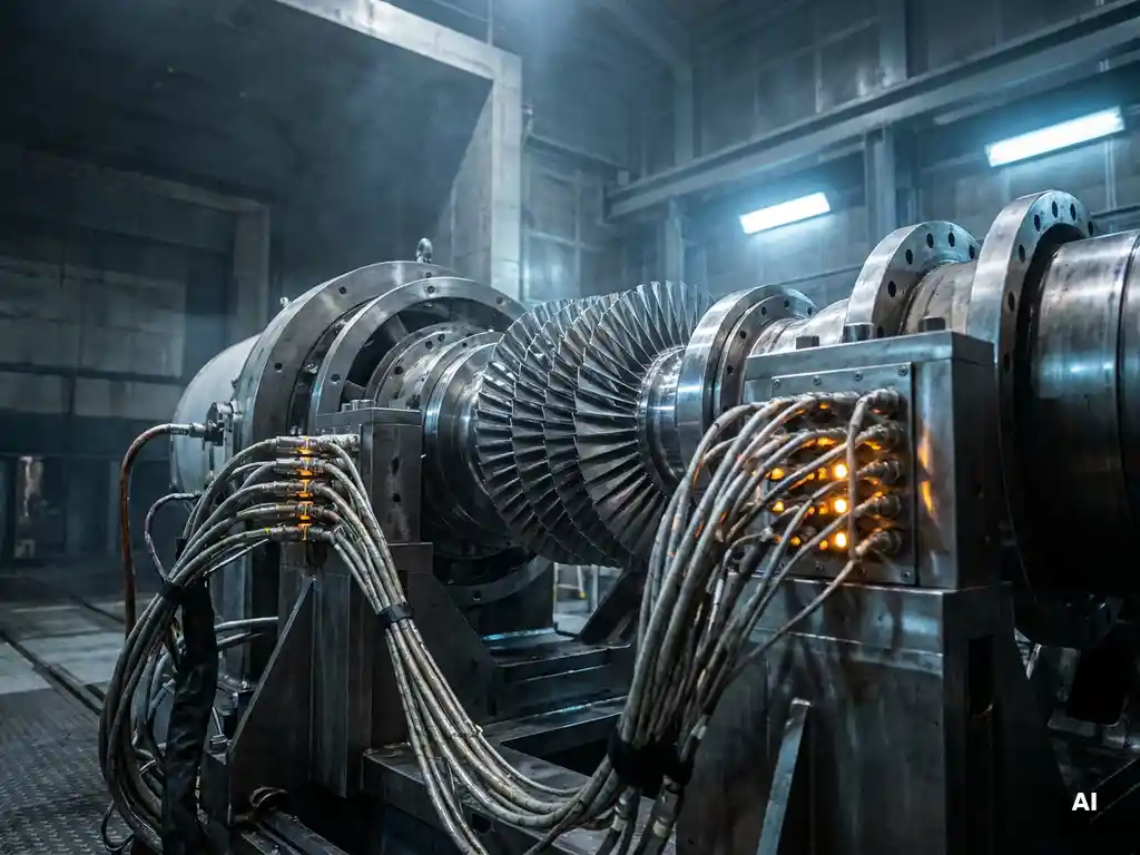
Engineers account for environmental conditions during component validation by applying correction factors to raw test data, controlling or characterising the test environment, and selecting facilities that can reproduce the thermodynamic and aerodynamic conditions representative of real engine operation. Without these measures, test results measured at one set of ambient conditions cannot be reliably compared against design targets or data from other facilities. The sections below address the specific questions that come up most often in aerothermal and compressor testing practice.
What environmental factors affect component validation results?
The environmental factors that most directly affect component validation results are ambient temperature, pressure, humidity, and air density. These variables change the thermodynamic state of the working fluid entering a test article, which in turn shifts the aerodynamic and thermal behaviour of the component away from the conditions assumed in the design.
In aero engine testing, even modest changes in ambient temperature alter the speed of sound, which affects Mach number matching. Variations in atmospheric pressure shift the mass flow and pressure ratio at which a compressor or turbine naturally operates. Humidity adds a further complication because moist air has different thermodynamic properties than dry air, and its effect on acoustic measurements is significant enough that it cannot be ignored in fan noise testing. Altitude above sea level also matters: a facility at higher elevation operates at lower ambient pressure, which changes the Reynolds number of the flow through the test article at a given rotational speed.
None of these factors invalidates a test on its own, but they all have to be measured accurately and accounted for before the data can be used with confidence.
How do engineers correct raw test data for ambient conditions?
Engineers correct raw test data for ambient conditions by applying non-dimensional correction groups, most commonly referred to as corrected speed and corrected mass flow. These correction factors scale the measured values to a standard reference condition, typically an International Standard Atmosphere (ISA) sea-level day, so that results from different test days and different facilities can be directly compared.
The corrections are derived from similarity theory. Because the aerodynamic behaviour of a compressor or turbine is governed by dimensionless parameters rather than absolute values, dividing rotational speed by the square root of the inlet total temperature and normalising mass flow by inlet total pressure and temperature remove the influence of day-to-day ambient variation. The same principle applies to pressure ratio and efficiency, which are already dimensionless.
In practice, the correction process requires high-quality inlet measurements. If the total pressure or total temperature at the component inlet is measured with significant uncertainty, the corrected performance map shifts accordingly, and the correction can introduce more error than it removes. This is why instrumentation design and calibration are as important as the correction methodology itself.
What is the difference between indoor and outdoor component testing environments?
The key difference between indoor and outdoor component testing environments is control and repeatability. Outdoor test rigs are exposed to ambient weather variation, background noise, wind, and precipitation, all of which introduce variability that is difficult to separate from the component’s true performance. Indoor facilities allow engineers to monitor and characterise the test environment precisely, and in some cases to control it.
For acoustic measurements in particular, outdoor testing on an airfield provides naturally low background noise and the free-field propagation conditions needed for valid sound power measurements. However, outdoor tests are weather-dependent and cannot be scheduled reliably year-round in most climates. An anechoic chamber replicates free-field acoustic conditions indoors by lining the walls, floor, and ceiling with sound-absorbing material that suppresses reflections to below 1% across the relevant frequency range. This makes acoustic results independent of weather while preserving the propagation conditions that make the data meaningful.
For aerodynamic and thermodynamic testing, an enclosed facility gives engineers the ability to instrument the inlet flow carefully, shield the test article from wind gusts, and maintain stable operating conditions over a long data acquisition window. These advantages are why dedicated aerospace test facilities are built indoors even when the cost is substantially higher than an open-air rig.
How do test facilities simulate real engine operating conditions?
Test facilities simulate real engine operating conditions by matching the non-dimensional parameters that govern aerodynamic and thermal similarity, primarily Mach number, Reynolds number, and, where relevant, temperature ratio. Matching these parameters at reduced pressure or temperature allows a component to be tested at manageable power levels while still producing data that is representative of the full-scale engine environment.
In compressor testing, the facility supplies conditioned air at a controlled inlet total pressure and temperature. The test rig is driven to the corrected speed that matches the target Mach number at each operating point, and the throttle position is adjusted to sweep the mass flow range of interest. For combustor and turbine testing, the facility must also supply heated air or hot gas at the correct inlet temperature ratios, which requires significantly more infrastructure.
Acoustic simulation adds another layer. A fan test in an anechoic chamber must replicate the inlet and exhaust flow conditions that the fan would experience in a nacelle, including the correct mass flow rate and the absence of upstream distortion, so that the noise sources generated are representative of flight conditions rather than an artefact of the test setup.
Why do Reynolds number and Mach number matter in component validation?
Reynolds number and Mach number matter in component validation because they govern the two dominant physical mechanisms in turbomachinery flows: compressibility and viscous effects. A component tested at the wrong Mach number will experience different shock structures, flow separation patterns, and pressure distributions than it would in the engine. A component tested at the wrong Reynolds number will have different boundary layer behaviour, which affects loss, heat transfer, and the onset of separation.
For compressors, Mach number matching is generally the higher priority because the stage loading and pressure ratio are directly tied to the velocity triangles, which depend on the ratio of blade speed to the local speed of sound. Reynolds number becomes the dominant concern at low corrected speeds, where the flow is more viscous in character, and in high-altitude cruise conditions where the reduced air density lowers the Reynolds number significantly compared to sea-level operation.
In gas turbine component testing, it is rarely possible to match both parameters simultaneously at reduced scale or reduced pressure. Engineers document the departure from full-scale similarity and apply correction methods or computational tools to estimate the performance at the true engine condition. The magnitude of this correction, and its uncertainty, forms part of the overall measurement uncertainty budget for the test.
How is measurement uncertainty managed in aerothermal testing?
Measurement uncertainty in aerothermal testing is managed through a combination of sensor calibration, redundant instrumentation, careful facility characterisation, and formal uncertainty analysis applied to every derived performance parameter. The goal is to quantify how much the reported result could differ from the true value, so that the data can be used with a known level of confidence in design decisions.
Calibration against traceable reference standards is the foundation. Pressure transducers, thermocouples, and flow measurement devices are calibrated before and after a test campaign, and any drift is factored into the uncertainty estimate. Redundant sensors at the same measurement location allow engineers to detect outliers and assess the spatial uniformity of the flow, which is itself a source of uncertainty if the inlet conditions are not uniform.
Facility characterisation addresses the systematic errors introduced by the test environment itself: inlet flow distortion, heat loss through duct walls, leakage paths, and the response time of the instrumentation relative to the speed of transient events. Each of these contributes to the uncertainty in the corrected performance parameters, and each has to be estimated through dedicated calibration tests or computational analysis rather than assumed to be negligible.
Formal uncertainty propagation then combines the individual sensor uncertainties and systematic error estimates into an overall uncertainty band for quantities such as isentropic efficiency or total pressure ratio. This band is reported alongside the performance map and tells the customer how much confidence they can place in the result when comparing it to their design target.
How AneCom AeroTest supports environmental condition management in component testing
AneCom AeroTest provides the infrastructure, instrumentation expertise, and data correction methodology needed to deliver aerothermal test results that are valid across a wide range of ambient conditions. The company’s Compressor Test Center in Wildau is equipped to conduct multistage compressor and fan testing under carefully characterised inlet conditions, with a modular measurement system that supports high-channel-count data acquisition across multiple test benches.
- Europe’s largest anechoic chamber (1,000 m² footprint, 10 m height) suppresses acoustic reflections to below 1% from 200 Hz to 40 kHz, replicating free-field conditions regardless of weather
- Full instrumentation services including sensor selection, calibration, and installation, ensuring that inlet and exit conditions are measured with the accuracy needed for reliable data correction
- Engineering analysis covering corrected performance maps, Reynolds number sensitivity, and formal measurement uncertainty quantification
- Support for combustor and turbine testing through cooperation partner facilities, extending environmental condition management to all aerothermal components of a gas turbine
- On-site and customer-site services worldwide, including instrumentation and assembly support for test campaigns outside the Wildau facility
If you are planning a compressor, fan, or aerothermal component test campaign and need a facility that can deliver corrected, uncertainty-quantified performance data under controlled environmental conditions, contact AneCom AeroTest to discuss your test requirements.
Related Articles
- What causes mechanical design problems in complex rotating assemblies?
- How do you interpret the results of a Pugh matrix?
- How does a Pugh matrix help engineers select a design concept?
- How do engineers know when a mechanical design is complete?
- What are the main design risks in high-speed rotating machinery?