
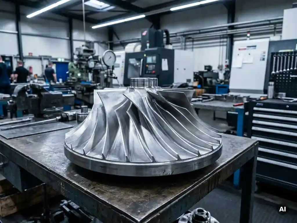
Rotational speed has a direct and significant effect on mechanical component design because it determines the magnitude of centrifugal forces, thermal loads, and dynamic stresses that a component must withstand throughout its service life. Higher RPM demands tighter tolerances, more capable materials, and more rigorous validation. The sections below address the key engineering questions that arise when designing rotating components for demanding applications such as gas turbines and aero-engine compressors.
What mechanical forces does rotational speed generate in a spinning component?
Rotational speed generates centrifugal stress as the dominant mechanical force in a spinning component. As angular velocity increases, every mass element within the component experiences an outward radial force proportional to the square of the rotational speed. This means that doubling the RPM quadruples the centrifugal load, which is the single most consequential relationship in the structural design of rotating machinery.
Beyond centrifugal stress, rotation introduces several other force types that engineers must account for. Coriolis forces act on fluid or gas passing through rotating passages, influencing flow behaviour in compressor and turbine stages. Gyroscopic moments resist changes in the orientation of the spin axis and become significant in any application where the rotor assembly is subject to manoeuvring loads. Thermal gradients, amplified by the frictional and aerodynamic heating that accompanies high-speed rotation, generate thermomechanical stresses that superimpose on the centrifugal field.
In gas turbine design, the combination of centrifugal stress and thermal stress in turbine discs and blades represents one of the most demanding structural problems in engineering. The stress state is not uniform across the component geometry, which is why detailed finite element analysis is essential before any physical hardware is manufactured.
How does RPM influence material selection for rotating parts?
RPM engineering requirements drive material selection primarily through the need for a high strength-to-density ratio. Because centrifugal stress scales with both rotational speed squared and material density, a lighter material at the same strength level reduces the centrifugal load it generates on itself. This is why titanium alloys dominate compressor stages and nickel superalloys are specified for high-temperature turbine sections, despite their cost and processing complexity.
At moderate rotational speeds, high-strength steels remain viable for structural discs and shafts where weight is less critical than stiffness and cost. As design targets push toward higher tip speeds and operating temperatures, the material envelope narrows considerably. Ceramic matrix composites are increasingly evaluated for turbine applications precisely because they offer low density combined with high-temperature capability, though their brittleness introduces different failure mode considerations that affect the overall design approach.
Fatigue properties are equally important in material selection. A material may have adequate static strength at the design RPM but insufficient resistance to the cyclic loading that occurs during engine start cycles, throttle changes, and transient manoeuvres. The interaction between rotational speed, temperature, and cyclic frequency defines the fatigue damage accumulation rate and therefore the component’s certified life.
What is the relationship between rotational speed and fatigue life?
Higher rotational speed reduces fatigue life because it raises the mean stress level on which cyclic loads are superimposed. Under the Goodman or Haigh fatigue frameworks used in aerospace component design, an increase in mean stress reduces the allowable alternating stress amplitude for a given target life. A component spinning faster therefore has less margin to accommodate the vibratory stresses that are always present in real operating conditions.
The relationship is not simply linear. Fatigue life is sensitive to stress concentration factors at features such as bolt holes, fillet radii, and blade attachment slots. At higher RPM, the stress at these geometric discontinuities rises proportionally, and the local stress may cross into a regime where fatigue crack initiation accelerates disproportionately. This is why compressor disc designs invest heavily in optimising fillet geometry and surface finish at attachment features, where the stress concentration combines with the centrifugal mean stress to create the most fatigue-critical conditions.
Thermal cycling compounds the problem. In aero engines, each flight cycle involves a cold start, a high-power climb phase, and a cool-down on the ground. The thermal strains introduced during these transients add to the mechanical fatigue damage, a combined loading mode known as thermomechanical fatigue. Accurate life prediction requires test data that captures both the mechanical and thermal components of the damage cycle, which is why aerothermal component testing is an integral part of the certification process.
How does rotational speed affect rotor dynamic behaviour and vibration?
Rotational speed determines whether a rotor operates below, at, or above its critical speeds, which are the rotational frequencies at which the shaft’s natural bending frequencies coincide with the excitation frequency. Passing through a critical speed causes a resonance condition where vibration amplitudes can increase sharply. Rotor dynamic design aims to place critical speeds away from sustained operating RPM ranges and to ensure that any unavoidable passage through a critical speed during run-up or shutdown occurs quickly enough to limit the energy input.
Unbalance is the primary source of rotational excitation. Even small asymmetries in mass distribution generate a rotating force at once-per-revolution frequency, and the response of the rotor to this force depends on how close the operating speed is to a critical speed. Precision balancing reduces the unbalance force, but it cannot eliminate it entirely, which is why rotor dynamic analysis must account for residual unbalance across the full operating speed range.
Blade and vane passing frequencies introduce additional aerodynamic excitation at integer multiples of the rotational frequency. In multi-stage compressors, the interaction between rotating blades and stationary vanes generates pressure disturbances that can excite blade bending and torsional modes. Managing these interactions requires careful attention to stage matching and blade count selection during the aerodynamic design phase, long before the first hardware is built.
What design trade-offs arise when optimising a component for higher rotational speeds?
Optimising a component for higher rotational speeds requires trading structural margin against aerodynamic performance, weight, and cost. Thicker disc webs and larger blade roots provide the structural capacity needed to carry higher centrifugal loads, but they add weight, which itself increases the centrifugal load and reduces the net benefit. The design converges on a minimum-weight geometry that just meets the structural requirements, leaving little margin for later modifications without a full re-analysis.
Higher tip speeds generally improve the pressure ratio achievable per compressor stage, which is aerodynamically desirable because it reduces the number of stages needed for a given overall pressure ratio. However, higher tip speeds also increase the relative Mach number at the blade leading edge, which introduces shock losses and raises the aerodynamic design complexity considerably. The trade-off between stage loading and efficiency is one of the central decisions in compressor design for aerospace applications.
Manufacturing tolerances become tighter at higher rotational speeds because the sensitivity of stress and vibration response to geometric variation increases. A blade that is slightly heavier than nominal contributes more to disc stress at high RPM than at low RPM, which means that the acceptable manufacturing spread on blade mass must narrow as design speeds rise. This directly affects production cost and yield rates.
How is rotational speed validated during component testing?
Rotational speed is validated during component testing through a combination of spin rig testing, aerodynamic performance testing, and structural instrumentation. Spin rig tests subject isolated discs and bladed assemblies to their full design speed in a controlled vacuum or low-pressure environment, allowing engineers to verify that stress levels, deformation patterns, and burst margins match predictions without the complexity of full aerodynamic loading.
During aerodynamic rig testing, speed is measured continuously using shaft encoders or non-contact optical systems that provide precise RPM data throughout the test matrix. Strain gauges bonded to blades or discs transmit stress data via telemetry or slip rings, allowing direct comparison between measured and predicted stress distributions at each tested speed point. Tip clearance probes monitor the radial growth of rotating components as speed increases, validating the thermal and centrifugal deflection models used during design.
Vibration validation requires dedicated resonance surveys, typically conducted by sweeping rotational speed slowly across the operating range while measuring blade and rotor vibration response. These surveys identify any resonance crossings that were not predicted in the design phase and confirm that vibration amplitudes at sustained operating speeds remain within acceptable limits. For gas turbine development programmes, this test data forms part of the evidence package submitted to airworthiness authorities.
How AneCom AeroTest supports rotating component development
AneCom AeroTest provides specialist testing and engineering services for rotating components across the full development cycle, from early design validation through to certification testing. The company’s capabilities are directly relevant to the challenges described throughout this article:
- Multistage compressor and fan testing at the Compressor Test Center, covering aerodynamic performance, rotor dynamic behaviour, and structural response across the full RPM operating range
- Aerothermal component testing for combustors and turbine parts, capturing the combined mechanical and thermal loading conditions that govern fatigue life in high-speed rotating hardware
- Instrumentation and data acquisition using a modular measurement system across three test benches, providing high-fidelity stress, vibration, and tip clearance data to validate design predictions
- Non-destructive testing services to assess the structural integrity of rotating components after testing or field operation, without requiring component disassembly
- Engineering analysis and design support, including finite element stress analysis and rotor dynamic modelling, available as a standalone service or integrated with physical testing
If your programme involves rotating components that need to be validated at realistic operating speeds and loading conditions, contact the AneCom AeroTest team to discuss how their test facilities and engineering expertise can support your development timeline.