
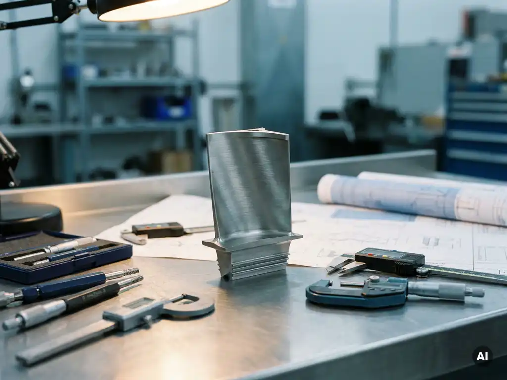
The detailed mechanical design phase is where an aero engine or gas turbine component moves from a validated concept into a fully defined, manufacturable design. Engineers produce complete geometry specifications, material selections, tolerance definitions, and assembly instructions that a manufacturer can act on directly. The sections below unpack the specific activities, analyses, reviews, and testing connections that make up this phase.
What activities make up the detailed mechanical design phase?
The detailed mechanical design phase covers the full definition of every component and assembly in a system. Engineers translate concept-level decisions into precise drawings, 3D models, material specifications, and manufacturing instructions. The phase ends when the design package is complete enough to hand off to a manufacturer or test team without further interpretation.
In practice, this involves several parallel workstreams. Geometry is finalised in CAD, with every feature dimensioned and toleranced. Material grades are confirmed against operating conditions, availability, and cost. Interfaces between components are resolved so that parts from different suppliers or design teams fit together correctly. Fastener selections, surface finish requirements, and coating specifications are all documented at this stage.
Assembly sequences are also worked out in detail, because a component that is well designed in isolation can still be impossible to assemble in a real engine environment. Weight budgets are tracked and signed off. Manufacturing feasibility is reviewed, often with input from the production team, to confirm that the design can actually be made within the intended process and tolerance capability.
How does detailed mechanical design differ from conceptual design?
Conceptual design establishes what a component will do and how it will broadly achieve that function. Detailed mechanical design defines exactly how it will be built. Where conceptual design deals in approximations and trade-off decisions, the detailed phase removes ambiguity and produces a complete, unambiguous technical definition.
During conceptual design, engineers might select a compressor stage count, set target pressure ratios, or choose between material families. Detailed design takes those choices and works out every consequence: the exact aerofoil profiles, the precise hub and casing geometry, the specific alloy grade, the machining tolerances, and the inspection criteria. Decisions that were held open during concept work must be closed.
The level of analysis also changes. Concept-phase calculations are often one-dimensional or based on empirical correlations. Detailed design typically involves higher-fidelity finite element analysis, computational fluid dynamics at component level, and fatigue life assessments that account for the actual geometry rather than a simplified approximation. For aerospace applications, this shift in fidelity is particularly significant because margins are tight and certification requirements demand documented evidence for every design decision.
What engineering analyses are performed during this phase?
Detailed mechanical design draws on a range of engineering analyses to confirm that the component will perform safely and reliably throughout its intended service life. The specific analyses depend on the component type, but for aero engine and gas turbine parts the workload is substantial.
Structural analysis using finite element methods is standard. Engineers assess stress distributions under operating loads, including centrifugal forces, pressure loads, thermal gradients, and vibration. For rotating parts such as compressor discs or turbine blades, burst margin calculations and low-cycle fatigue assessments are required. High-cycle fatigue is addressed through forced-response analysis, which examines how the component responds to periodic excitation from adjacent blade rows or combustion pressure fluctuations.
Thermal analysis is equally important for hot-section components. Cooling effectiveness must be quantified, and temperature distributions feed back into the structural analysis because material properties change significantly with temperature. Creep behaviour, which describes how a material deforms slowly under sustained load at high temperature, must be assessed for turbine components operating near material limits.
Aerodynamic analysis at detailed design level refines the performance predictions made during concept work. For compressor and fan designs, this includes three-dimensional CFD to capture secondary flow effects, tip clearance sensitivity, and off-design behaviour. Acoustic analysis may also be performed at this stage, particularly for fan systems where noise certification requirements place hard limits on radiated sound levels.
What design reviews take place and who is involved?
Design reviews during the detailed mechanical design phase serve as formal checkpoints where the design team, customer representatives, and subject matter experts assess whether the design is ready to proceed. The most common formal review at this stage is the Critical Design Review, which confirms that the detailed design is complete and that all open issues have been resolved or formally accepted.
Before the Critical Design Review, many programmes hold interim reviews at subsystem or component level. These allow problems to be caught and resolved before the full system design is locked. Preliminary reviews earlier in the programme will have addressed the concept and system architecture; by the detailed design phase, reviews focus on the specific geometry, analysis results, and manufacturing plan.
The people involved typically include the lead design engineers, stress and thermal analysts, aerodynamicists, materials specialists, manufacturing engineers, and the customer’s technical authority. For certified products, a representative from the relevant airworthiness authority may also attend or receive the review documentation. Independent reviewers from outside the immediate design team are often included to provide a check on assumptions that the core team may have normalised over time.
Review outputs include a list of actions with owners and due dates, formal acceptance or conditional acceptance of the design, and documented evidence that the design meets its requirements. This documentation becomes part of the certification evidence package for gas turbine programmes subject to regulatory approval.
How does detailed mechanical design connect to component testing?
Detailed mechanical design and component testing are closely linked because the design produces the test articles and the test results feed back into the design. Testing is used to validate analysis predictions, identify unexpected behaviour, and generate the experimental data that supports certification. A design that cannot be tested is difficult to certify, so testability is considered during the design phase itself.
Test vehicles are designed in parallel with the production component, and instrumentation requirements are defined at this stage. The number and location of pressure taps, thermocouples, strain gauges, and optical access ports must be planned into the hardware before it is manufactured. For compressor and fan rigs, the test article geometry must be representative of the production design while also accommodating the measurement systems needed to capture the data.
The connection runs in both directions. Analysis models are calibrated against test data from earlier programmes or from subcomponent tests. Where test results reveal discrepancies with predictions, the design may be updated, and the analysis model is revised to reflect the new understanding. This iterative loop between design and test is a normal part of development, not a sign that the original design was inadequate.
How AneCom supports the detailed mechanical design phase
AneCom AeroTest provides engineering and testing services that directly support teams working through the detailed mechanical design phase of aero engine and gas turbine development. Rather than offering design work in isolation, AneCom integrates design, instrumentation, and experimental validation into a single service, which means that test requirements are considered from the start and test hardware is built to generate the data the design team actually needs.
- Design and analysis services covering structural, thermal, and aerodynamic assessment of compressor, combustor, and turbine components
- Instrumentation design and integration for test articles, including pressure, temperature, and acoustic measurement systems
- Assembly and preparation of test vehicles at the Wildau facility or at customer sites worldwide
- Experimental testing on dedicated compressor and fan rigs, including Europe’s largest anechoic chamber for acoustic validation
- Non-destructive testing services to assess components before and after test runs
If your programme is approaching a Critical Design Review or preparing test articles for component validation, contact AneCom to discuss how the team can support your specific design and test requirements.
Related Articles
- What are the most common mistakes during mechanical concept development?
- What is the difference between Design for Manufacture and Design for Assembly?
- What is detailed design in mechanical engineering?
- How can engineers determine whether a prototype is manufacturable?
- Why is tolerance management important in rotating assemblies?