
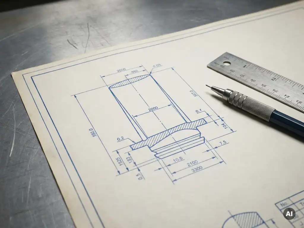
A mechanical engineering drawing must contain a title block, dimensioned geometry, tolerances, material and surface finish specifications, and references to the applicable drawing standard. These elements work together to give any qualified engineer or manufacturer everything needed to produce or inspect a part without ambiguity. The sections below address the most common questions engineers and procurement teams ask when working with technical drawings.
What are the essential components of a mechanical engineering drawing?
A complete mechanical engineering drawing contains five core elements: the drawing geometry (views and projections of the part), dimensions and tolerances, material and surface finish callouts, a title block, and a reference to the governing drawing standard. Every element serves a distinct function, and omitting any one of them forces the reader to make assumptions that introduce manufacturing risk.
The drawing geometry uses orthographic projections, sections, and detail views to communicate the three-dimensional shape of a part in two dimensions. First-angle and third-angle projection are the two conventions in common use, and the drawing must indicate which one applies. Section views expose internal geometry that would otherwise be hidden, while detail views zoom into areas where dimensions are too dense to read clearly at the main scale.
Beyond geometry, the drawing must specify what the part is made from, how its surfaces should be finished, and what tolerances govern each dimension. A drawing that carries geometry alone is incomplete because a manufacturer cannot select a process, choose a material, or set up inspection without that information. For applications in aerospace engineering, where component performance under extreme conditions is non-negotiable, the completeness of a drawing directly affects whether a part will pass validation.
What information does a title block contain?
A title block is a structured table, typically placed in the lower-right corner of a drawing, that records the administrative and technical metadata for the document. It identifies the part name, part number, drawing number, revision level, scale, material, projection angle, applicable standard, the company or organization responsible, and the names and dates of the drafter, checker, and approver.
The revision block within or adjacent to the title block is particularly important in a production environment. It logs every change made to the drawing, including what changed, when, and who authorized it. Without a clear revision history, a manufacturer working from an outdated drawing revision may produce parts that no longer conform to the current design intent.
Some title blocks also include a general tolerance note, which defines default dimensional tolerances that apply to any dimension not individually toleranced on the drawing. This avoids the need to specify a tolerance on every single dimension while still ensuring the drawing is unambiguous.
How are dimensions and tolerances specified on a technical drawing?
Dimensions on a technical drawing are expressed as linear or angular values placed along dimension lines, with arrowheads indicating the extent of measurement. Tolerances define the permissible variation from the nominal dimension and are specified either as bilateral values (plus or minus a range), unilateral values (variation in one direction only), or through a geometric dimensioning and tolerancing (GD&T) framework.
GD&T, governed by ASME Y14.5 in the United States and ISO 1101 internationally, communicates not just size tolerances but also form, orientation, location, and runout requirements. A flatness callout, for example, constrains how much a surface may deviate from a perfect plane, independently of where that surface sits in space. This level of specificity is necessary for parts that must mate or move relative to other components.
Datum references are a central part of the tolerance scheme. A datum is a theoretically exact point, axis, or plane from which measurements are taken, and it anchors the tolerance framework to the physical part. Without clearly defined datums, two inspectors measuring the same part may reach different conclusions about whether it conforms.
What do surface finish and material callouts mean on a drawing?
Surface finish callouts specify the texture of a machined or processed surface, typically expressed as a roughness value (Ra or Rz) in micrometers or microinches. The symbol placed on a surface in the drawing tells the manufacturer the maximum allowable roughness and sometimes the direction of the surface lay. Material callouts identify the specific alloy, grade, or specification the part must be made from, often referencing a standard such as an ASTM, DIN, or AMS designation.
Surface finish matters because roughness affects friction, fatigue resistance, sealing performance, and corrosion behavior. A hydraulic seal face requires a much smoother finish than a structural bracket, and specifying the wrong value in either direction wastes machining time or produces a part that fails prematurely in service.
Material callouts go beyond simply naming a metal or polymer. In precision engineering contexts, the callout may specify heat treatment condition, temper designation, minimum mechanical properties, or traceability requirements. For components used in gas turbine development, the material specification is often tied directly to the qualification test data that validates the part for its operating environment. AneCom’s engineering services include design and analysis work where material selection and drawing specifications are developed in parallel with the test requirements.
What drawing standards govern mechanical engineering drawings?
Mechanical engineering drawings are governed by national and international standards that define projection methods, dimensioning rules, tolerancing conventions, and title block requirements. The principal standards are ISO 128 (general drawing principles), ISO 2768 (general tolerances), ASME Y14.5 (dimensioning and tolerancing), and ASME Y14.100 (engineering drawing practices). The applicable standard must be stated on the drawing itself.
ISO standards are widely used in Europe and internationally, while ASME standards are dominant in North America and in much of the aerospace and defense supply chain regardless of geography. When a drawing is exchanged between organizations in different regions, the stated standard removes any ambiguity about which projection angle, which tolerance philosophy, or which surface texture measurement method applies.
Industry-specific overlays also exist. Aerospace drawings frequently reference AS9100 quality management requirements or customer-specific drawing standards issued by OEMs. Defense programs often impose their own drawing requirements on top of the base standard. Understanding which standard governs a drawing is not optional; misreading a first-angle projection as third-angle, for instance, produces a mirror-image part.
What common mistakes cause mechanical engineering drawings to be rejected?
Engineering drawings are most commonly rejected for missing or conflicting tolerances, incomplete title blocks, undefined datums, incorrect or missing projection angle symbols, and surfaces or features left without a finish callout. Each of these gaps forces the manufacturer or inspector to request clarification, which delays production and increases cost.
Conflicting dimensions are a frequent problem on complex parts. When the same feature is dimensioned in two different views with slightly different values, the drawing is technically unmanufacturable because no single interpretation satisfies both callouts. Modern CAD tools reduce this risk, but they do not eliminate it, particularly when drawings are revised manually or when 2D drawings are derived from 3D models without careful checking.
Over-tolerancing is another common issue. Specifying tighter tolerances than the function of the part requires drives up manufacturing cost without any performance benefit. A drawing that calls out micron-level tolerances on non-critical features will either be questioned by the manufacturer or produced at unnecessary expense. Matching the tolerance to the actual functional requirement, informed by analysis and test experience, produces drawings that are both manufacturable and fit for purpose.
Incomplete revision control also causes rejection, particularly in regulated industries. A drawing without a current revision level and approval signature cannot be released for production under most quality management systems.
How AneCom supports precision engineering drawing and component validation
AneCom AeroTest works at the intersection of engineering design and experimental validation, supporting customers who need both technically complete drawings and the test data to back them up. For teams developing compressors, turbine components, or aerodynamic assemblies, AneCom provides:
- Design and analysis services that align drawing specifications with actual test and performance requirements
- Instrumentation and assembly expertise that translates drawing intent into physical test articles
- Aerothermal component testing that generates the validation data needed to confirm that a design, as drawn and built, performs within specification
- Non-destructive testing services for components where inspection requirements must be defined at the drawing stage
- Support for defence industry programs where drawing standards and traceability requirements are particularly demanding
If your team is working through drawing requirements for a gas turbine or aero engine component and needs engineering support from design through test, contact AneCom to discuss how their services can be structured around your program.
Related Articles
- How many design concepts should engineers evaluate before selecting one?
- What should be checked before a mechanical design is released for manufacturing?
- How do engineers generate concepts for complex mechanical systems?
- What are the most common mistakes during mechanical concept development?
- How do engineers know when a mechanical design is complete?