
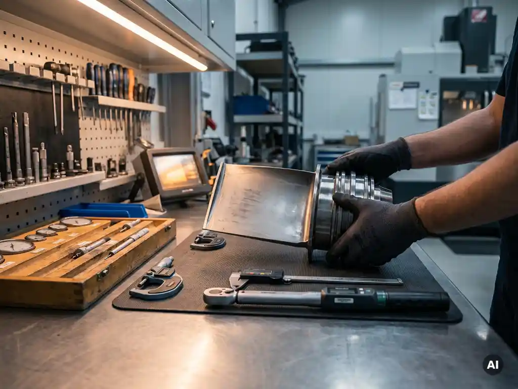
Engineers design complex machinery for easier assembly and maintenance by applying structured design principles from the earliest stages of development. The most effective approaches combine modular architecture, tolerance management, and instrumentation planning so that both first-time assembly and long-term servicing become predictable, repeatable processes. The sections below address the specific questions that arise when putting these principles into practice.
What design principles make complex machinery easier to assemble?
The core principles that make complex machinery easier to assemble are minimising part count, standardising interfaces, and designing for unambiguous orientation. When each component can only be fitted one way, and when the number of unique fasteners or connection types is kept low, assembly errors decrease and build time shortens considerably.
Beyond part reduction, accessibility is a governing principle. Every component that requires installation should be reachable with standard tooling, without requiring the removal of unrelated sub-assemblies. This sounds straightforward, but in high-density systems such as aero engines or gas turbines, spatial constraints regularly force trade-offs between aerodynamic efficiency and physical access. Resolving those trade-offs in favour of assembly access during the design phase is far less costly than reworking a design after production tooling has been committed.
Symmetry and self-locating features also matter. Components designed with datum surfaces, alignment pins, or keyed interfaces reduce the skill dependency of assembly and support consistent positioning across multiple builds. This consistency is what allows assembly to be validated and repeated reliably.
How does modular design reduce maintenance time on complex systems?
Modular design reduces maintenance time by allowing faulty or worn sub-assemblies to be removed and replaced as discrete units, without disturbing adjacent systems. Instead of diagnosing and repairing at the component level inside the machine, technicians can swap a module and return the system to service, then address the removed module separately.
This approach has measurable implications for availability. In rotating machinery, for example, a modular bearing housing or seal assembly can be exchanged during a scheduled window rather than requiring extended downtime for in-situ repair. The design investment required is real: modules need well-defined mechanical and functional boundaries, standardised connectors, and interfaces that tolerate the dimensional variation that accumulates over service life. However, that investment pays back across every maintenance event over the system’s operational lifespan.
Modular architecture also simplifies the logistics of spare parts. Rather than stocking individual components for every possible failure mode, operators can maintain a smaller inventory of interchangeable modules. For systems operating in remote or time-sensitive environments, that simplification carries significant practical value.
What role does instrumentation play in maintainability planning?
Instrumentation plays a direct role in maintainability planning by making internal system states observable without disassembly. Sensors positioned at key measurement points allow engineers and operators to monitor temperature, pressure, vibration, and flow, detecting degradation before it becomes a failure.
The placement of instrumentation is itself a design decision that affects maintenance. Sensors need to be accessible for calibration and replacement, and their wiring or signal paths should not obstruct access to the components they monitor. In practice, instrumentation routing is often treated as secondary to the primary mechanical layout, which creates maintenance problems later. Treating sensor access as a first-class design requirement from the outset avoids this.
In development testing, instrumentation density is typically far higher than in production hardware. Data gathered during rig testing of gas turbine components informs decisions about which parameters genuinely need monitoring in service and where sensors should be located for reliable readings. That testing phase is where the trade-off between instrumentation coverage and mechanical complexity gets resolved with real data rather than assumptions.
How can tolerance and clearance design affect assembly accuracy?
Tolerance and clearance design directly determine whether components assemble to the intended geometry, and whether that geometry is achievable consistently across production builds. Tolerances that are too tight increase manufacturing cost and rejection rates; tolerances that are too loose allow variation to accumulate through a stack-up, degrading functional performance.
Tolerance stack-up analysis is the method used to quantify this risk. By mapping out the chain of dimensions that contribute to a critical assembly gap or alignment, engineers can calculate the worst-case and statistical variation at the final interface. In rotating machinery, where running clearances between blade tips and casings are measured in fractions of a millimetre, this analysis is not optional. A clearance that is too tight causes contact and damage; one that is too generous reduces aerodynamic efficiency.
Clearance design also interacts with thermal expansion. Components that operate across wide temperature ranges change dimensions in service, and the clearances specified at assembly must account for those changes. Designing for the correct clearance at operating temperature, rather than at ambient assembly temperature, requires careful material selection and thermal modelling alongside the geometric tolerance analysis.
What is the difference between design for assembly and design for manufacture?
Design for assembly (DFA) focuses on how components come together to form a finished product, optimising the process of joining, fitting, and securing parts. Design for manufacture (DFM) focuses on how individual components are produced, optimising geometry, tolerances, and material choices so that each part can be made efficiently and consistently.
The two disciplines are related but address different stages and different constraints. A component designed purely for ease of manufacture might have features that complicate assembly, such as symmetrical geometry that makes orientation ambiguous, or a shape that requires a specialised fixture to hold during installation. Conversely, a design optimised for assembly might specify part geometries that are difficult or expensive to machine.
In practice, DFA and DFM need to be developed in parallel, with the design team actively resolving conflicts between the two sets of requirements. This is most effective when manufacturing and assembly engineers are involved during concept development rather than receiving a completed design for review. Early cross-functional involvement is what turns DFA and DFM from separate checklists into an integrated design process.
How does early-stage testing validate assembly and maintenance design decisions?
Early-stage testing validates assembly and maintenance design decisions by exposing problems when design changes are still low-cost. Physical prototypes, rig tests, and component-level experiments reveal whether assembly sequences work as planned, whether tolerances produce the intended fit, and whether maintenance access is genuinely achievable in practice.
Analytical tools such as digital mock-ups and simulation can identify many issues before hardware is built, but they do not capture everything. The physical experience of assembling a component under realistic conditions, with real tooling and real spatial constraints, consistently surfaces problems that analysis misses. Maintenance simulation, where technicians perform representative service tasks on a prototype, is particularly effective at identifying access problems and tool interference that are invisible in a CAD model.
For aerothermal components such as compressor stages, combustors, and turbine sections, rig testing also validates that the assembly geometry produces the intended aerodynamic and thermal performance. A compressor stage assembled with blade tip clearances at the upper tolerance limit will perform differently from one assembled at the lower limit. Testing across that range, rather than assuming nominal performance, produces validation data that reflects what production hardware will actually deliver.
How AneCom AeroTest supports assembly and maintenance engineering
AneCom AeroTest provides engineering services that directly support design for assembly and maintainability decisions in gas turbine and aero engine development. Specific capabilities include:
- Instrumentation design and installation for component and system-level test vehicles, supporting the measurement planning that informs both development testing and in-service monitoring strategies
- Assembly and preparation of complex test hardware at the Compressor Test Center in Wildau, including multistage compressor systems and fan rigs, where assembly quality directly affects test data validity
- Aerothermal component testing that generates validation data for compressors, combustors, and turbine parts across the full operating range, supporting tolerance and clearance decisions with measured performance data
- Non-destructive testing services that support maintenance planning and condition assessment without disassembly
- Engineering services delivered from a single source, covering design, analysis, instrumentation, and testing, including support at customer sites worldwide
If your programme requires test-based validation of assembly or maintenance design decisions for gas turbine or aero engine components, contact AneCom AeroTest to discuss how the facility and engineering team can support your development objectives.