
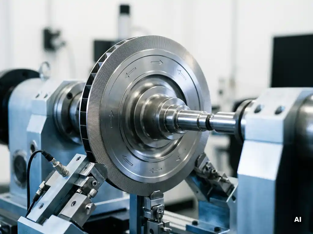
Loads on rotating components in aero engines are defined by identifying and quantifying every mechanical, thermal, and dynamic force that acts on a part during its full operating life. This process combines analytical methods, computational modelling, and experimental data to build a load spectrum that represents both normal operation and worst-case conditions. The sections below address the specific questions engineers most commonly ask when working through this process.
What types of loads act on rotating components in aero engines?
Rotating components in aero engines experience four primary categories of load: centrifugal loads from rotational speed, thermal loads from temperature gradients, aerodynamic loads from gas path pressures and flow forces, and vibratory loads from dynamic excitation. Each category acts simultaneously during engine operation, and the design process must account for their combined effect rather than treating them in isolation.
Centrifugal loads dominate in high-speed rotating parts such as compressor and turbine discs, where the outward force generated by rotation can reach tens of thousands of times the component’s own weight. Thermal loads arise because temperature varies significantly across a component, creating differential expansion and internal stress. Aerodynamic loads are imposed by the gas path, including pressure differences across blade surfaces and unsteady flow effects. Vibratory loads, while sometimes smaller in magnitude, are responsible for a large proportion of fatigue damage because they cycle continuously at high frequency throughout an engine’s service life.
For aerospace applications, the load environment is further complicated by transient events such as takeoff, throttle changes, and emergency deceleration, all of which generate load combinations that differ substantially from steady cruise conditions.
How are centrifugal loads calculated for rotating parts?
Centrifugal loads are calculated from the fundamental relationship between rotational speed, component mass, and the radial distance of that mass from the axis of rotation. The centrifugal force on any mass element equals the product of its mass, the square of the angular velocity, and its radial position. Because force scales with the square of rotational speed, even modest increases in operating speed produce significant increases in centrifugal stress.
In practice, engineers apply this principle through finite element analysis (FEA), which divides a component into thousands of small elements and computes the stress state across the entire geometry. For a turbine disc, the analysis must capture the stress concentration at blade attachment features such as fir-tree slots, where local stresses can be many times higher than the average section stress. The disc bore, where material accumulates to resist the outward pull of the blades, is another critical location that FEA highlights reliably.
The calculation also depends on an accurate mass model of the component, which requires precise knowledge of material density and geometry. Any deviation between the design model and the manufactured part, such as machining tolerances or material inhomogeneity, must be assessed to confirm that the actual component remains within acceptable stress limits at all operating speeds.
What role do thermal loads play in rotating component design?
Thermal loads arise from temperature gradients within a rotating component and produce stress through constrained differential expansion. When one region of a part is hotter than an adjacent region, the hotter material tries to expand more but is restrained by the cooler surrounding material, generating internal stress without any external force being applied. In gas turbine components, these gradients can be steep and change rapidly during transient operating conditions.
Turbine blades and discs are the components most affected by thermal loading. Blade surfaces exposed to hot combustion gas can reach temperatures close to the material’s melting point, while the blade root, cooled by compressor air, remains substantially cooler. This temperature difference creates a bending moment in the blade and a radial stress distribution in the disc that must be superimposed on the centrifugal stress field.
Transient thermal loads are often more damaging than steady-state conditions because the temperature gradients are at their steepest during rapid power changes. A cold start or a rapid throttle advance subjects the material to thermal shock, and repeated cycling of this kind drives low-cycle fatigue. Engineers therefore analyse the full mission cycle, not just the cruise condition, to capture the cumulative thermal damage contribution.
How do engineers account for vibratory and dynamic loads?
Engineers account for vibratory and dynamic loads by identifying the natural frequencies of rotating components, mapping the excitation sources present in the engine, and ensuring that resonant crossings either do not occur at operating speeds or are traversed quickly enough to limit the accumulated fatigue damage. The primary tool for this work is a Campbell diagram, which plots natural frequencies against rotational speed and identifies where engine excitation orders intersect component resonances.
Excitation sources in an aero engine include the periodic pressure pulses generated by upstream and downstream blade rows, combustion pressure fluctuations, and mechanical imbalance. Each source excites the component at a frequency that is a multiple of the shaft speed, and if that frequency coincides with a structural natural frequency, the resulting resonant vibration can produce stress amplitudes far exceeding those from centrifugal loading alone.
Material damping and aerodynamic damping both help limit resonant response, but neither can be relied upon to prevent fatigue damage if a strong resonance is present throughout normal operation. Where a resonance cannot be avoided by geometry changes, engineers apply mistuning strategies, in which small intentional variations in blade geometry or mass break the perfect periodicity of the bladed disc and distribute vibratory energy more evenly, reducing peak stress in any single blade.
What is the difference between limit loads and ultimate loads in rotating component design?
Limit loads are the maximum loads a rotating component is expected to experience during its certified operating life, including all defined manoeuvre, environmental, and failure conditions. Ultimate loads are derived by multiplying limit loads by a safety factor, typically 1.5 in aerospace practice, and the component must sustain ultimate loads without fracture, even if permanent deformation occurs. The distinction matters because the design must satisfy different criteria at each level.
At the limit load level, the component must remain fully functional with no permanent deformation. At the ultimate load level, structural integrity must be maintained but functionality is no longer required, because ultimate loads represent extreme events from which continued operation is not expected. This two-tier approach provides a structured margin against uncertainty in load prediction, material properties, and manufacturing variation.
For rotating components in gas turbine applications, the limit load definition must also address burst containment requirements, where a disc or blade failure must not result in uncontained debris penetrating the engine casing. This drives additional structural requirements beyond the standard limit and ultimate load framework.
How does experimental testing validate load assumptions for rotating components?
Experimental testing validates load assumptions by measuring actual stress, strain, temperature, and vibration response under controlled conditions and comparing the results against analytical predictions. Strain gauges bonded to rotating parts transmit data via telemetry, while optical and non-contact measurement techniques allow surface temperature and displacement to be captured without physical contact. Where predictions and measurements agree, confidence in the load model increases; where they diverge, the model is revised before the design is released.
Component rig testing, where an isolated compressor stage or turbine assembly is run at representative speeds and pressure ratios, provides load data that cannot be obtained from full engine tests alone. Rig tests allow instrumentation to be applied more extensively, operating conditions to be varied systematically, and failure modes to be explored safely in a controlled environment.
Acoustic and aerodynamic measurements during fan and compressor testing also contribute to the vibratory load picture, because unsteady pressure fields in the gas path are a primary source of blade excitation. Capturing these fields experimentally, rather than relying solely on computational fluid dynamics predictions, gives engineers a more reliable basis for assessing fatigue loads on compressor blades and fan stages.
How AneCom supports rotating component load definition
AneCom AeroTest provides experimental validation services that directly support the load definition process for rotating components in aero engines and gas turbines. The company’s capabilities are specifically structured to close the gap between analytical load assumptions and measured physical behaviour:
- Aerothermal component testing on dedicated compressor, combustor, and turbine test benches, generating measured pressure, temperature, and flow data that feed directly into stress and fatigue load models
- Comprehensive instrumentation services, including strain gauge installation and telemetry on rotating parts, enabling direct measurement of mechanical loads during rig operation
- Fan system testing in Europe’s largest anechoic chamber, where unsteady aerodynamic excitation forces on fan blades can be characterised under acoustically controlled free-field conditions
- Non-destructive testing of turbine blades and other rotating components to assess material condition and detect defects that would alter a component’s response to applied loads
- Design and analysis services that integrate test data with computational models, refining load assumptions iteratively as experimental evidence accumulates
All services are available from a single source, including on-site support at customer facilities worldwide. To discuss how AneCom AeroTest can support your rotating component development programme, contact the team directly.
Related Articles
- What are the main stages of mechanical prototype development?
- What information is needed before mechanical concept design can begin?
- What happens during the detailed mechanical design phase?
- How can engineers determine whether a prototype is manufacturable?
- How does rotational speed affect mechanical component design?