
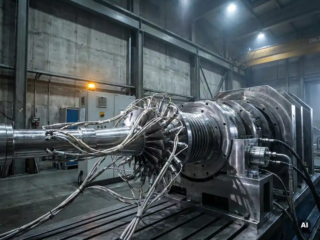
Engineers design representative load cases by combining real engine operating data, aerodynamic boundary conditions, and structural requirements into a defined set of test points that replicate the thermal, mechanical, and flow conditions a component experiences in service. The goal is to produce validation data that reflects genuine engine behavior, not idealized or arbitrary conditions. The sections below work through the key decisions that shape this process, from input selection to post-test verification.
What inputs do engineers use to define load cases?
Engineers define load cases using a combination of engine cycle data, component performance maps, structural load spectra, and customer-specified requirements. These inputs collectively describe the range of conditions a component must survive and perform within, giving the test program a physical and contractual basis.
The starting point is typically the engine cycle, which defines how parameters such as pressure ratio, mass flow, rotational speed, and inlet temperature vary across the full operational envelope, from ground idle to maximum takeoff. From this cycle, engineers extract the aerodynamic boundary conditions that bound the component’s expected operating range.
Structural requirements add another layer. Blade stress maps, thermal gradients, and fatigue life targets derived from finite element analysis all inform which operating points are mechanically significant, not just aerodynamically interesting. A point that sits at moderate aerodynamic loading may still be critical if it coincides with a resonant frequency or a peak thermal gradient.
Customer specifications and airworthiness standards also shape the input set. For aerospace engine development, regulatory requirements define minimum test coverage, and OEM-specific design rules add further constraints. The result is a matrix of conditions that must be tested, from which engineers then select the most representative points.
How do engineers select which operating points are truly representative?
Engineers select representative operating points by identifying which conditions produce the highest aerodynamic loading, the greatest structural stress, or the most demanding thermal environment, and then confirming that those points can be reproduced accurately on the test rig. Representativeness is defined by physical severity, not by operational frequency alone.
A common approach is to map the full performance space and identify candidate points at or near the stability boundary, peak efficiency, and design intent. Engineers then apply sensitivity analysis to determine which variables drive component behavior most strongly. If a small change in inlet temperature produces a large shift in blade loading, that temperature range becomes a priority test condition.
Operability margins also influence selection. Points near the surge line for a compressor, or near the lean blowout limit for a combustor, are included even if the engine spends little time there during normal operation, because they define the boundaries of safe performance. Validation data at these extremes is what gives confidence in the component’s real-world robustness.
What’s the difference between rig-level and engine-level load cases?
Rig-level load cases are defined by what the test facility can physically deliver, while engine-level load cases describe what the component actually experiences inside a running engine. The two are related but rarely identical, and translating between them is one of the more demanding tasks in test program design.
At the rig level, engineers work within the constraints of available pressure supply, temperature range, mass flow capacity, and rotational speed limits. A compressor test rig, for example, may not be able to replicate the exact inlet distortion pattern seen in a fully assembled engine, so engineers develop an equivalent condition that produces the same aerodynamic effect on the component being tested.
Engine-level load cases include installation effects, inter-component interactions, and transient phenomena that are difficult or impossible to reproduce in isolation. The bleed air extraction patterns, the downstream pressure imposed by a turbine, and the thermal soak of surrounding structure all influence how a component behaves in service. Rig testing captures the dominant effects; engine testing validates the assembly.
The practical consequence is that rig-level load cases are often defined with correction factors or scaling rules that account for the differences. Engineers document these assumptions explicitly, because the validity of the validation data depends on how well those corrections hold.
How does instrumentation influence load case design?
Instrumentation constraints directly shape which load cases can be tested and how precisely they can be characterized. If a sensor cannot survive a particular temperature or pressure, that operating point may need to be approached indirectly or excluded from the test matrix entirely.
The choice of measurement technique determines the spatial and temporal resolution of the data. High-frequency pressure transducers, for instance, can capture unsteady aerodynamic events that steady-state probes miss entirely. If unsteady loading is relevant to the validation objective, the instrumentation plan must include sensors capable of resolving it, and the load cases must be defined to excite those phenomena.
Sensor placement also feeds back into load case selection. Engineers design the test matrix to ensure that the most heavily instrumented sections of the component pass through their peak loading conditions during the test, so that the data captured is actually useful for model correlation. A load case that produces peak stress in an uninstrumented region yields limited validation value.
For gas turbine component testing, the interaction between instrumentation and load case design is managed iteratively. Pre-test analysis identifies the expected flow field, and the instrumentation layout is then optimized to capture the features that matter most. This process sometimes reveals that additional operating points are needed to fully characterize a particular flow structure.
What role does acoustic testing play in load case validation?
Acoustic testing contributes to load case validation by capturing noise emission data that reflects the aerodynamic and mechanical state of a component at a given operating point. For fan systems in particular, the acoustic signature is a direct indicator of flow quality, blade loading distribution, and tonal noise sources, making it a meaningful validation metric alongside aerodynamic performance data.
Fan noise is generated by the interaction between rotor wakes and downstream stators, by inlet distortion, and by blade surface pressure fluctuations. Each of these mechanisms is sensitive to the aerodynamic load case. A test point that sits at design intent will produce a characteristic acoustic spectrum; deviations from that spectrum can indicate that the component is not operating as predicted, even when conventional performance measurements appear acceptable.
Acoustic measurements are most informative when conducted under conditions that eliminate reflections and environmental interference. Anechoic test facilities suppress wall reflections, allowing engineers to measure the true far-field noise signature of the fan or compressor under test. This is particularly relevant when validating low-noise design features, where the difference between a successful and unsuccessful design may be a few decibels across a narrow frequency band.
The load cases selected for acoustic validation therefore need to cover not just the aerodynamic design point but also the off-design conditions where noise generation mechanisms change character. Approach and cutback power settings, for example, are acoustically significant even though they represent moderate aerodynamic loading.
How do engineers verify that a load case has been met during testing?
Engineers verify that a load case has been met by comparing the measured boundary conditions at the test article inlet and outlet against the target values specified in the test plan, within defined tolerance bands. If the measured conditions fall within those bands, the test point is accepted as representative; if not, the point is repeated or the data is flagged for correction.
The verification process relies on real-time monitoring of key parameters during the test run. Flow rate, total pressure, total temperature, and rotational speed are typically controlled and logged continuously. Automated control systems adjust the facility operating point to maintain the target conditions, and the data acquisition system records when the rig has stabilized within tolerance.
Post-test analysis adds a further verification layer. Engineers compare the measured performance characteristics, such as pressure ratio and efficiency, against pre-test predictions. Significant deviations prompt an investigation into whether the load case was correctly achieved or whether the component behavior was genuinely different from the prediction. This distinction matters for how the data is used in subsequent analysis and model updating.
For structural load cases, verification extends to confirming that the measured strain, vibration, or temperature distributions match the expected patterns. Strain gauge data and thermocouple readings are compared against finite element predictions, and any discrepancies are reviewed before the test point is accepted as validated.
How AneCom supports component validation testing
AneCom AeroTest provides end-to-end support for aerothermal component validation, covering the full chain from load case definition through instrumentation, testing, and data delivery. Specifically, AneCom offers:
- Multistage compressor and fan testing at the Compressor Test Center in Wildau, with controlled boundary conditions across a wide range of operating points
- Acoustic fan testing in Europe’s largest anechoic chamber, with wall reflection below 1% from 200 Hz to 40 kHz, enabling precise noise signature measurement across all relevant load cases
- Full instrumentation design, manufacture, and installation, including high-frequency pressure sensing and thermal measurement suited to demanding aerothermal environments
- Access to combustor and turbine test capabilities through established cooperation partners, extending coverage to all major gas turbine components
- Non-destructive testing and post-test inspection services to verify component condition after validation runs
For development programs where load case fidelity directly affects the validity of certification data, working with a facility that controls both the test environment and the instrumentation from a single source reduces the risk of systematic error. To discuss how AneCom can support your next validation program, get in touch with the team directly.
Related Articles
- How do engineers define acceptance criteria for component testing?
- What is the difference between qualification testing and acceptance testing?
- How do engineers develop a risk-based validation strategy for critical components?
- How do you interpret the results of a Pugh matrix?
- How are interfaces managed in complex mechanical assemblies?