
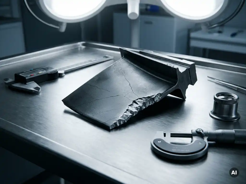
The most common failures in component validation testing fall into four broad categories: instrumentation errors, mechanical failures, data quality issues, and design-related shortcomings. Each category can compromise test results in different ways, and understanding which failure type has occurred determines whether a test can be salvaged or must be restarted from scratch. The sections below address the specific questions engineers and test managers encounter most often when failures arise during aero engine and gas turbine component testing.
What types of failures occur most often during component validation?
In component validation testing, the most frequently occurring failures are instrumentation errors, followed by mechanical failures during the test run and data quality problems that only become apparent during post-processing. Design failures, where the component itself does not meet performance targets, are less common but carry the most significant downstream consequences for development programmes.
The distribution of failure types tends to shift depending on the maturity of the test article. Early-stage validation testing, where a component is being evaluated for the first time, sees more design-related failures because assumptions made during analysis have not yet been confirmed experimentally. Later-stage testing, where a refined design is being validated against specification, more often encounters instrumentation and data quality failures, since the component itself is generally well understood. In aerothermal testing environments, all four failure types can occur within a single test campaign, and separating their effects requires careful post-test analysis.
Why do instrumentation errors cause so many test failures?
Instrumentation errors are the leading cause of failed or compromised validation tests because measurement systems in aero engine and gas turbine testing operate under extreme conditions. High temperatures, high pressures, vibration, and rotating machinery create an environment where sensors, signal cables, connectors, and data acquisition systems are all subject to physical stress that can degrade or destroy measurement integrity during the test itself.
The challenge is that many instrumentation failures are not immediately visible. A pressure transducer that has shifted its calibration due to thermal cycling will still return a signal, but the values it produces will be systematically offset from reality. Similarly, a thermocouple that has developed an intermittent connection may produce plausible-looking temperature traces that are nonetheless corrupted. These silent failures are particularly damaging because they can pass initial quality checks and only surface when results are compared against expected performance ranges or cross-checked against independent measurements.
Rigorous pre-test calibration, redundant sensor placement, and real-time data monitoring during the test run are the primary defences against instrumentation-driven test failure. In compressor testing, for example, placing multiple pressure taps at the same axial station allows engineers to detect sensor outliers during the test and flag suspect channels before they contaminate the full dataset.
How do mechanical failures during testing differ from design failures?
A mechanical failure during testing refers to a physical breakdown of the test article, test rig, or supporting hardware during the test run itself, such as blade damage, seal failure, or structural fatigue of a test fixture. A design failure, by contrast, means the component completes the test intact but does not meet its performance targets, revealing that the underlying design did not achieve what analysis predicted.
The distinction matters because the response to each failure type is different. A mechanical failure typically requires physical inspection, repair or replacement of the damaged component or rig element, and a root cause investigation before testing can resume. A design failure requires analysis of the test data, comparison against simulation models, and engineering decisions about whether to modify the design, adjust the test conditions, or accept the result as within an acceptable tolerance band.
Mechanical failures during gas turbine component testing can also generate secondary data problems. A blade that partially fails mid-test may alter the aerodynamic conditions seen by downstream instrumentation, meaning that data collected after the mechanical event is no longer representative of the intended test condition. Identifying the exact point in the test timeline where the mechanical failure occurred is therefore an important step in determining which portions of the dataset remain valid.
What causes data quality failures in aerothermal testing?
Data quality failures in aerothermal testing arise when the raw measurements collected during a test cannot be converted into reliable validation test data. The most common causes are signal noise from electromagnetic interference, insufficient sampling rates for unsteady phenomena, incorrect boundary condition measurements, and post-processing errors introduced during data reduction.
Aerothermal testing environments are particularly demanding for data quality because the quantities being measured, including total pressure, total temperature, flow angle, and heat flux, are often sensitive to small changes in probe positioning, flow uniformity, and thermal equilibration. A total pressure probe that is not fully aligned with the local flow direction will underread, and the magnitude of the error depends on the local Mach number and flow angle, both of which vary across the measurement plane. In combustor and turbine testing, where temperature gradients are steep and flow fields are highly three-dimensional, achieving consistent data quality across all measurement points requires careful attention to probe design, positioning, and the sequence in which measurements are taken.
Data quality can also be compromised by facility-level effects rather than the test article itself. Upstream flow non-uniformities, leakage in the test section, or thermal drift in reference instrumentation can all introduce systematic errors that are difficult to separate from genuine component behaviour without a well-designed test matrix that includes reference conditions and repeatability checks.
How can acoustic and aerodynamic test failures be prevented?
Acoustic and aerodynamic test failures can be prevented through facility design that eliminates extraneous noise and flow disturbances, combined with a test plan that systematically controls boundary conditions before acquiring primary measurements. In fan and compressor acoustic testing, the most effective prevention measure is conducting tests in an anechoic environment that suppresses reflections from facility walls, allowing measurements to represent true free-field acoustic behaviour.
For aerodynamic testing, the most common source of preventable failure is insufficient characterisation of the inlet conditions presented to the test article. If the velocity profile, turbulence intensity, or swirl at the component inlet does not match the design intent, the component will operate in a condition it was not designed for, and the resulting performance data will not be representative of engine conditions. Pre-test inlet surveys, conducted before the test article is installed, are a standard method for confirming that the facility is delivering the correct aerodynamic environment.
In acoustic testing specifically, the frequency range and dynamic range of the measurement system must be matched to the expected noise sources. For aero engine fan testing, this typically means coverage from low-frequency tonal noise associated with blade passing up to high-frequency broadband noise, across a dynamic range that can capture both the loudest tones and the quietest broadband components without clipping or noise floor limitations.
When should a failed validation test be repeated versus redesigned?
A failed validation test should be repeated when the failure is attributable to the test setup, instrumentation, or facility rather than to the component design itself. It should lead to a redesign when the test data clearly shows that the component’s performance does not meet specification and the gap cannot be explained by measurement uncertainty or test conditions alone.
The decision requires an honest assessment of what the test data actually shows. If a significant portion of the instrumentation failed, or if the test conditions drifted outside the specified operating envelope, then the test has not produced valid evidence about the component’s performance, and repeating it under corrected conditions is the appropriate response. Attempting to draw design conclusions from a test that was not properly controlled wastes development time and can lead to incorrect engineering decisions.
When the test was well-controlled and the data is of acceptable quality, a performance shortfall points toward the design rather than the test. In this case, repeating the test without design changes will reproduce the same result, which is not a useful expenditure of test time or budget. The engineering team needs to determine whether the performance gap is within the range that can be addressed by calibration or minor adjustment, or whether it requires a substantive design change before the next test campaign.
In practice, many failed tests contain elements of both scenarios: some instrumentation channels may be invalid while others are trustworthy, or the test may have captured useful data over part of the operating range while conditions were unrepresentative at others. Careful data screening, combined with clear acceptance criteria agreed before the test, makes these judgements more systematic and less dependent on individual interpretation.
How AneCom AeroTest supports component validation testing
AneCom AeroTest provides end-to-end support for component validation testing, addressing the failure modes described above through a combination of facility capability, engineering expertise, and rigorous test management. Specific capabilities relevant to preventing and resolving validation test failures include:
- Instrumentation design and installation for high-temperature, high-pressure aerothermal environments, with redundancy strategies built into the measurement plan
- Europe’s largest anechoic chamber for fan acoustic testing, eliminating facility reflection as a source of acoustic test failure
- Multistage compressor testing at the Compressor Test Center in Wildau, with a modular measurement system across three test benches for reliable data acquisition
- Non-destructive testing services that support post-test inspection of components following mechanical events during a test campaign
- Full data reduction and analysis services to distinguish genuine performance shortfalls from instrumentation or facility-related data quality issues
AneCom AeroTest also offers engineering services that cover design, instrumentation, assembly, and testing from a single source, including at customer sites. If you are planning a validation test campaign or need support following an inconclusive or failed test, contact the team to discuss the specific requirements of your programme.
Related Articles
- How do engineers define acceptance criteria for component testing?
- What validation evidence is required before aerospace components can be approved?
- What does a prototype engineer do during product development?
- How can prototype development reduce technical risk before testing?
- What causes mechanical design problems in complex rotating assemblies?