
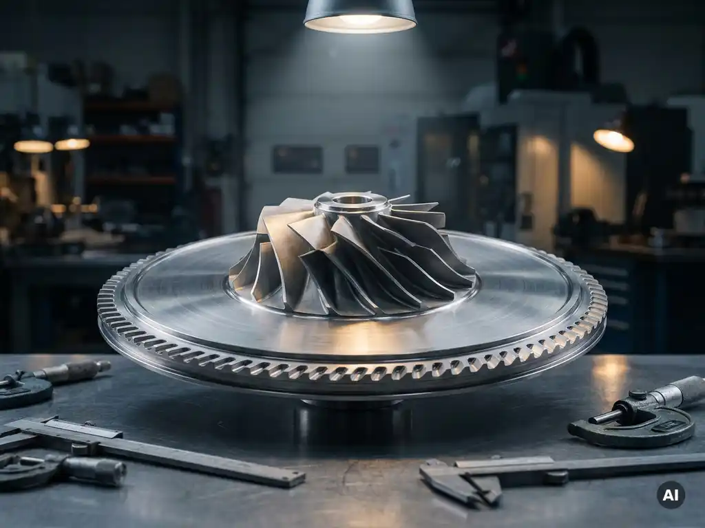
Mechanical design for highly loaded rotating systems changes fundamentally because the forces, temperatures, and dynamic behaviours involved exceed what standard structural design methods can address. Components like compressor rotors and turbine discs operate under centrifugal loads, thermal gradients, and aerodynamic excitation simultaneously, requiring a design approach built around fatigue life, resonance avoidance, and material behaviour at extreme conditions. The sections below address the specific questions engineers and researchers most commonly face when working with this class of machinery.
What mechanical forces make highly loaded rotating systems uniquely challenging?
Highly loaded rotating systems are uniquely challenging because they combine multiple force types that act simultaneously and interact with each other. Centrifugal stress, aerodynamic pressure, thermal stress, and vibratory loading all occur at once, and the combined effect on a component is far more demanding than any single load would suggest on its own.
Centrifugal force is typically the dominant load in aero-engine mechanical design. As a rotor spins, every element of mass generates a radially outward force proportional to the square of rotational speed. At the tip speeds typical of modern compressor or turbine stages, this produces blade root stresses that can approach the yield strength of the material. The design must accommodate this without permanent deformation or crack initiation across the intended service life.
Aerodynamic loading adds a bending component to the blade, varying in magnitude and direction as flow conditions change across the operating envelope. This variation creates a cyclic load history that accumulates fatigue damage over time. When centrifugal and aerodynamic loads combine with thermal gradients, the resulting stress field is three-dimensional and transient, making accurate prediction genuinely difficult without detailed computational analysis and physical validation.
How does material selection change under extreme rotational loads?
Material selection for highly loaded rotating components is governed by the need to maximise specific strength (strength relative to density) while maintaining adequate fatigue resistance, creep resistance, and damage tolerance. Lower density allows higher rotational speeds for the same centrifugal stress level, which is why titanium alloys dominate compressor stages and nickel superalloys are used in turbine sections where temperature resistance is the primary constraint.
In compressor mechanical design, titanium alloys offer a strong strength-to-weight ratio and acceptable fatigue performance at moderate temperatures. Towards the rear stages of a high-pressure compressor, where air temperatures rise significantly through compression, the titanium may be replaced by nickel-based alloys or specialised steels that retain mechanical properties at higher temperatures.
For turbine blade stress management, nickel superalloys with directional solidification or single-crystal microstructures are selected specifically to eliminate grain boundaries in the direction of maximum centrifugal load. This removes a primary site for creep deformation and fatigue crack initiation, extending component life in the most thermally and mechanically demanding environment in the engine. Coating systems are applied to manage surface oxidation and thermal exposure, but the base alloy selection remains the primary structural decision.
What role does resonance play in rotating system design?
Resonance is one of the most serious concerns in gas turbine rotor design because rotating components are continuously exposed to periodic aerodynamic excitation. If a blade or disc natural frequency coincides with an excitation frequency at an operating speed, the resulting vibration amplitude can cause high-cycle fatigue failure within a very short time, sometimes within minutes of sustained operation at that condition.
Aeromechanical design challenges related to resonance are addressed using Campbell diagrams, which map structural natural frequencies against engine speed and overlay the excitation orders generated by upstream and downstream blade rows, struts, and other flow disturbances. The goal is to ensure that no natural frequency intersects a significant excitation order within the operating speed range, or that where crossings cannot be avoided, the aerodynamic damping and structural damping are sufficient to keep vibration amplitudes within acceptable limits.
Mistuning, the intentional or manufacturing-induced variation in blade properties within a rotor, is a related consideration. A perfectly tuned rotor (all blades identical) can exhibit localised vibration modes where energy concentrates in a small number of blades, greatly amplifying stress. Controlled mistuning can break this energy localisation and distribute vibration more evenly, improving the overall fatigue margin of the assembly.
How do thermal gradients affect structural integrity in rotating components?
Thermal gradients in rotating components produce differential thermal expansion that generates internal stress even in the absence of mechanical loading. When one region of a disc or blade heats faster than adjacent material, the hotter region wants to expand but is constrained by the cooler surrounding material, introducing compressive stress in the hot region and tensile stress elsewhere. These thermally induced stresses combine directly with centrifugal and aerodynamic stresses.
During transient operation, such as rapid acceleration or deceleration, thermal gradients are at their most severe. The bore of a turbine disc, which is thermally shielded and has high thermal mass, heats and cools more slowly than the rim, which is directly exposed to hot gas. This creates a cyclic thermal strain at the bore that, repeated over the engine’s service life, drives low-cycle fatigue. Disc life is often limited by this mechanism rather than by peak steady-state stress.
Cooling design in turbine blades directly addresses this problem by reducing the metal temperature and flattening temperature gradients across the wall thickness. Film cooling, internal convective passages, and thermal barrier coatings each contribute to reducing the thermal load on the structural material, but they also introduce their own stress concentrations at cooling holes and coating interfaces that must be assessed as part of the overall structural analysis.
What design and analysis methods are used to validate rotating system integrity?
Validating rotating system integrity requires a layered approach combining analytical methods, numerical simulation, and physical testing. No single method provides complete assurance on its own, and the confidence in a design grows as evidence from multiple independent sources converges.
Finite element analysis (FEA) is the primary numerical tool for calculating stress distributions in complex three-dimensional geometries under combined mechanical and thermal loading. Modern FEA models of a turbine blade or compressor disc can include millions of elements and resolve stress concentrations at cooling holes, fillet radii, and attachment features. These results feed directly into fatigue life calculations using material data from specimen testing.
Computational fluid dynamics (CFD) provides the aerodynamic pressure and temperature boundary conditions that drive the structural analysis. Coupled aerothermal-structural analyses, where CFD and FEA exchange data iteratively, are increasingly used to capture the interdependence between flow behaviour and component deformation, particularly in cases where blade shape changes under load affect aerodynamic performance.
Spin testing in a dedicated rig subjects a rotor to its design speed under controlled conditions, validating burst margin and confirming that the assembly behaves as predicted. Strain gauge measurements during spin testing provide direct comparison against FEA predictions. For aerospace rotating components, this physical validation is a regulatory and engineering requirement, not an optional step.
How does testing on a compressor rig capture real-world mechanical behaviour?
Compressor rig testing captures real-world mechanical behaviour by reproducing the aerodynamic loading, rotational speeds, and thermal conditions that a component will experience in service, while allowing detailed measurement that is impossible on a complete engine. A rig test can isolate specific stages or configurations, enabling systematic investigation of mechanical response under controlled and repeatable conditions.
Instrumentation is central to the value of rig testing for rotating system fatigue assessment. Strain gauges bonded to rotating blades transmit data via telemetry or slip rings, recording the actual stress cycles experienced during different operating conditions. These measurements validate the predictions from FEA and aeromechanical models, and they can identify unexpected excitation sources or stress concentrations that were not captured in the analysis phase.
Tip timing systems, which use optical or capacitive probes mounted in the casing to measure blade arrival times, provide a non-contact alternative for detecting blade vibration amplitude and frequency during operation. This technique is particularly valuable for mapping resonance crossings across the full speed range and for monitoring blade health during extended endurance tests. The combination of contact and non-contact measurement methods on a compressor rig gives a comprehensive picture of mechanical behaviour that cannot be obtained from analysis alone.
For gas turbine development programmes, rig testing at representative aerodynamic conditions provides the validation data needed to clear a design for engine integration, reducing the risk of discovering mechanical problems at a later and more costly stage of development.
How AneCom AeroTest supports mechanical design validation for rotating systems
AneCom AeroTest provides experimental validation services specifically for the rotating systems described throughout this article. The company’s Compressor Test Center in Wildau near Berlin is equipped to test multistage compressor systems and aero-engine fans under representative aerodynamic conditions, with instrumentation capability spanning strain gauge telemetry, tip timing, and full aerothermal measurement.
- Aeromechanical testing to characterise blade vibration, resonance crossings, and fatigue loading under real operating conditions
- Aerothermal component testing covering compressors, combustors, and turbine assemblies, providing the boundary condition data needed for coupled structural analyses
- Full instrumentation, assembly, and test execution managed from a single source, reducing coordination complexity for development programmes
- Non-destructive testing and inspection services to assess component condition before and after mechanical testing
- Support available at AneCom facilities and at customer sites worldwide, covering the full range of engineering and testing services
If you are working on a compressor or turbine development programme and need experimental data to validate your mechanical design, contact AneCom AeroTest to discuss test planning and facility availability.
Related Articles
- What information is required before detailed design can start?
- How do engineering teams compare alternative mechanical concepts?
- What is design maturity in mechanical engineering?
- How can conflicting engineering requirements be handled during concept selection?
- How should engineering teams weight concept selection criteria?