
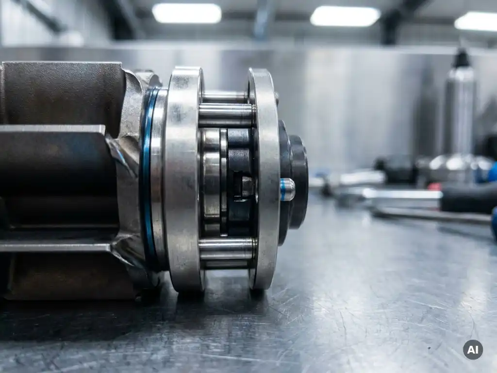
Interfaces in complex mechanical assemblies are managed through a structured process that defines, documents, and controls every point where components or subsystems meet. This process spans geometry, load transfer, thermal behaviour, and fluid flow, and applies across the full lifecycle from early design through final assembly and testing. The sections below address the most common questions around interface management in detail.
What types of interfaces exist in complex mechanical assemblies?
Interfaces in complex mechanical assemblies fall into several categories: mechanical, thermal, fluid, and electrical. A mechanical interface is any physical boundary where two or more components meet, transfer load, or constrain relative motion. In practice, most assemblies involve several interface types simultaneously, and managing them requires treating each type with its own set of requirements.
Mechanical interfaces include joints, fastener patterns, mating surfaces, and bearing fits. These govern how forces and moments are transmitted between parts and how dimensional tolerances accumulate through a stack. Thermal interfaces define how heat flows between components in contact or in close proximity, which matters particularly in high-temperature environments such as gas turbine assemblies where differential thermal expansion can alter clearances and preloads. Fluid interfaces appear wherever a flow path crosses a component boundary, including seals, ports, manifold connections, and labyrinth gaps. Each type of fluid interface must maintain its sealing function across the full operating range of pressure, temperature, and vibration.
In aerospace assemblies, these interface types rarely exist in isolation. A turbine stage, for example, presents mechanical interfaces at the blade root and disc, thermal interfaces across the cooling circuit boundaries, and fluid interfaces at the gas path seals, all of which interact with one another during operation.
How are interface requirements defined and documented?
Interface requirements are defined by translating top-level system performance requirements into specific constraints at each component boundary. The primary document for this is the Interface Control Document (ICD), which records the agreed geometry, loads, temperatures, flow conditions, and tolerance limits at each interface. An ICD is typically owned jointly by the teams responsible for the components on either side of the boundary.
The definition process begins at system level, where engineers allocate requirements to subsystems and identify which boundaries between subsystems carry functional significance. Each identified boundary becomes a controlled interface. Requirements at that boundary are then quantified: what loads must be transferred, what clearances must be maintained, what leak rates are acceptable, and under what environmental conditions. These quantified requirements flow down into part drawings, assembly procedures, and inspection criteria.
Good interface documentation is unambiguous about reference frames, datum structures, and measurement conditions. Vague statements such as “adequate clearance” are replaced with explicit numerical limits tied to defined temperature and load states. Version control of ICDs is treated with the same rigour as drawing releases, because an uncontrolled change to an interface requirement can propagate failures across multiple subsystems.
What causes interface failures in mechanical assemblies?
Interface failures in mechanical assemblies are most commonly caused by tolerance stack-up, thermal mismatch, inadequate surface preparation, or requirement changes that are not propagated to all affected documents. In most cases, a failure at an interface reflects a gap in the definition or verification process rather than a deficiency in any single component.
Tolerance stack-up occurs when individual part tolerances, each acceptable in isolation, accumulate in a way that places the assembled interface outside its functional limits. This is particularly problematic in multi-stage assemblies where many components sit in series. Thermal mismatch arises when adjacent components with different coefficients of thermal expansion change the contact pressure, clearance, or preload at an interface as temperature changes. A joint that is correctly assembled at room temperature may be overstressed or loose at operating temperature if the mismatch is not accounted for in the design.
Surface preparation failures, such as contamination, incorrect surface finish, or improper application of sealant or adhesive, compromise the interface locally even when the design intent is correct. Requirement drift is a subtler cause: when a design change is made to one component and the interface document is not updated, the adjacent component may no longer be compatible, and the discrepancy may not surface until assembly or test.
How does interface management differ across design and testing phases?
Interface management shifts in character as a programme moves from design to testing. During design, the focus is on definition and prediction: establishing what the interface must do, modelling how it will behave, and allocating tolerances. During testing, the focus moves to verification: confirming that the as-built interface performs within the defined limits and diagnosing any deviations that appear.
In the design phase, interface management is largely analytical. Engineers use geometric dimensioning and tolerancing (GD&T), finite element models, and thermal analyses to predict interface behaviour. Sensitivity studies identify which tolerances have the greatest influence on performance and where tighter control is warranted. At this stage, the ICD is a living document that is updated as the design matures.
During assembly and test, interface management becomes physical. Assembly procedures must specify the sequence in which interfaces are closed, the torque or preload applied to fasteners, and the inspection steps that confirm each interface is within tolerance before the assembly proceeds. In aerothermal component testing, where rig configurations must accurately replicate engine boundary conditions, interface management at the test hardware level directly affects the validity of the data. A poorly controlled interface between a test article and its rig can introduce flow leakage or thermal gradients that corrupt measurements. Testing and instrumentation services that account for interface conditions from the outset produce more reliable validation data.
What tools and methods are used to control assembly interfaces?
The primary tools for controlling assembly interfaces are GD&T on engineering drawings, tolerance analysis software, assembly models, and formal interface control documents. Together, these tools create a chain from design intent to physical verification that can be audited and updated as the programme evolves.
GD&T provides a standardised language for specifying geometry at interfaces, including form, orientation, location, and runout, in a way that is independent of measurement method. Tolerance analysis, whether done analytically or through Monte Carlo simulation, quantifies how individual tolerances combine and identifies the probability that an assembly will fall outside its functional limits. Three-dimensional assembly models allow engineers to visualise interface fits and detect clashes or gaps before hardware is made.
At the process level, assembly travellers and work instructions translate interface requirements into step-by-step actions for technicians. Torque specifications, alignment targets, and inspection hold points are embedded directly in the build sequence. Metrology, including coordinate measuring machines and laser trackers, is used to verify that critical interfaces meet their dimensional requirements after assembly. Non-destructive testing methods can assess interface integrity, for example by detecting insufficient bond in adhesive joints or fretting damage at contact faces, without disassembling the hardware.
Who is responsible for interface management in an assembly programme?
Responsibility for interface management is shared across several roles, but a designated interface manager or systems engineer typically holds overall accountability for ensuring that all interfaces are defined, controlled, and verified. No single design discipline owns all interface types, so coordination across structural, thermal, and fluid engineering teams is necessary.
At the programme level, a systems engineer or chief engineer defines the interface management process, maintains the master list of controlled interfaces, and arbitrates when requirements on either side of a boundary conflict. At the component level, the design engineer responsible for each part is accountable for meeting the interface requirements allocated to their component and for flagging any change that affects an interface boundary.
In practice, interface management works best when responsibility is explicitly assigned in the programme’s engineering plan and when the ICD has named owners on both sides of each boundary. Ambiguity about ownership is one of the most common reasons interface issues are discovered late, because neither team assumes the other has checked the boundary condition. For programmes that involve external suppliers or cooperation partners, a formal interface agreement between organisations, not just between internal teams, is necessary to maintain control.
How AneCom supports interface management in complex assemblies
AneCom AeroTest provides engineering and testing services that address interface management directly, from early design support through experimental validation. Working with gas turbine OEMs and defence customers, AneCom’s teams handle the instrumentation, assembly, and testing of complex aerothermal components where interface control at every stage is a prerequisite for valid test data.
- Design and analysis support that includes tolerance assessment and interface definition for compressor, combustor, and turbine test articles
- Precision assembly of test hardware with documented inspection steps at each critical interface
- Instrumentation engineering that accounts for interface conditions affecting measurement accuracy
- Non-destructive testing services to assess interface integrity without disassembly
- Aerothermal component testing in facilities designed to replicate engine boundary conditions at the hardware interfaces
If your programme requires interface management support across design, assembly, or test phases, contact AneCom AeroTest to discuss how the team can contribute to your validation programme.
Related Articles
- What is Design for Assembly and why does it matter?
- How can conflicting engineering requirements be handled during concept selection?
- When should Design for Manufacture be considered during product development?
- How are loads defined when designing rotating components?
- When should maintainability be considered during mechanical design?