
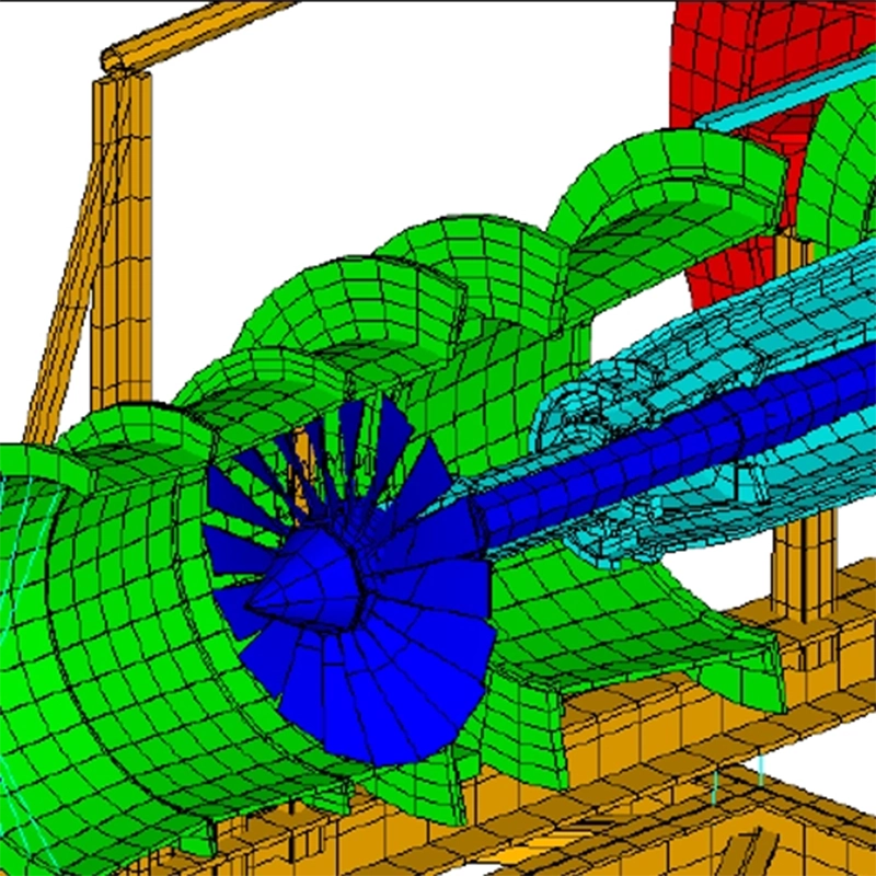
Interfaces are critical in rotating machinery design because they govern how individual components transfer mechanical loads, thermal energy, and dynamic forces across boundaries between parts. A poorly designed interface can compromise an entire assembly, even when each individual component meets its specification. The questions below unpack the specific ways interfaces shape performance, reliability, and test outcomes in aero engines and gas turbines.
What types of interfaces exist in rotating machinery?
Rotating machinery contains several distinct categories of mechanical interfaces, each serving a different structural or functional role. The main types are contact interfaces between mating surfaces, such as flanges, spigots, and bolted joints; fit interfaces that control radial or axial clearance between rotating and static parts; and dynamic interfaces where rotating components interact with seals, bearings, or adjacent stages under load.
In an aero engine, these interfaces appear throughout the entire gas path. Compressor blade roots sit in disc slots that form a dovetail or fir-tree interface, transmitting centrifugal loads into the disc. Stage-to-stage connections in a multi-stage compressor rely on flanged joints or curvic couplings to maintain concentricity and axial alignment. Bearing interfaces locate rotating shafts relative to the static casing, controlling radial position under varying thermal and mechanical conditions. Seal interfaces, including labyrinth seals and brush seals, manage leakage between high-pressure and low-pressure regions without physical contact during normal operation.
Each interface type carries its own design requirements. A bolted flange must maintain clamping force under thermal cycling. A blade root interface must distribute stress without fretting damage over thousands of operating cycles. Understanding which interface category is involved in a given assembly determines which failure modes to design against and which tolerances to specify.
How do interface tolerances affect rotating machinery performance?
Interface tolerances directly control clearances, contact pressure, and load distribution between mating components. Tolerances that are too loose allow relative motion between parts, causing fretting wear and reducing fatigue life. Tolerances that are too tight can prevent correct assembly, induce unwanted pre-stress, or cause seizure when thermal expansion closes the remaining clearance at operating temperature.
In compressor and turbine stages, small deviations in tolerance stack-up can shift blade tip clearance beyond acceptable limits. Tip clearance, the gap between a rotor blade tip and the surrounding casing, directly affects aerodynamic efficiency. A clearance that grows by even a fraction of a millimetre due to interface misalignment can measurably reduce stage pressure ratio and efficiency. This sensitivity means that tolerance analysis is not a secondary concern but a core part of the mechanical design process from the earliest stages.
Tolerance management also affects assembly repeatability. In a test environment, where components are assembled and disassembled repeatedly across multiple test runs, interface tolerances determine whether the assembly returns to the same mechanical state after each rebuild. Inconsistent reassembly introduces scatter into test data, making it harder to isolate the effect of a design change from variability introduced by the rebuild itself.
What happens when an interface fails in a gas turbine?
When an interface fails in a gas turbine, the consequences range from gradual performance degradation to sudden mechanical failure, depending on the interface type and the load it carries. A failed seal interface allows hot gas ingestion into disc cavities, raising local temperatures beyond material limits. A failed blade root interface can result in blade liberation, which is a high-energy event with the potential to cause cascading structural damage throughout the engine.
More commonly, interface failures develop gradually. Fretting at a bolted joint progressively removes material from mating surfaces, reducing clamping force and allowing micro-slip to increase. Fretting debris can become an abrasive contaminant in the flow path. A worn spigot interface loses its ability to maintain concentricity, introducing rotor imbalance that increases bearing loads and vibration amplitudes across the entire drivetrain.
The difficulty with interface failures is that the damage often occurs at a location that is not directly instrumented. A bearing interface may be monitored through vibration signatures, but the root cause of changing vibration levels is only confirmed through disassembly and inspection. This is one reason why engineering testing services that include thorough post-test teardown inspection are a standard part of development programmes for gas turbine components.
How does thermal expansion influence interface design choices?
Thermal expansion influences interface design because rotating machinery operates across a wide temperature range, from ambient conditions at startup to several hundred degrees Celsius at full power, and different materials expand at different rates. An interface designed with correct clearance at room temperature may close completely at operating temperature if the surrounding casing and the rotating shaft are made from materials with different coefficients of thermal expansion.
Designers manage this by selecting material pairings with compatible expansion characteristics, or by deliberately designing the cold clearance to accommodate the expected differential growth. In some cases, interference fits are used at assembly specifically because the fit will relax to the correct contact pressure once operating temperatures are reached. The reverse situation also occurs: a press fit that provides secure location at room temperature may become too tight at elevated temperature, generating stresses that exceed the yield strength of one or both components.
Thermal transients add another layer of complexity. During acceleration from idle to full power, the casing and the rotor do not heat up at the same rate. The casing, exposed to external airflow, may lag behind the rotor thermally, temporarily reducing tip clearances below their steady-state values. Interface designs must account for these transient conditions, not just the steady operating point, to avoid contact between rotating and static parts during normal engine cycles.
What role do interfaces play in compressor and fan testing?
In compressor and fan testing, interfaces play a dual role: they must replicate engine-representative mechanical boundary conditions so that test data is valid, and they must also accommodate the practical requirements of a test rig, which include instrumentation access, repeated assembly, and the ability to modify configurations between test runs.
A compressor test rig connects the test article to a drive system through shaft and coupling interfaces. If these interfaces introduce misalignment or additional stiffness that does not exist in the engine installation, the rotor dynamics of the test article will differ from engine behaviour. This can shift critical speeds, alter bearing loads, and change the vibration environment in ways that make the test data less representative.
Fan testing in an anechoic environment places specific demands on interfaces because acoustic measurements are sensitive to any mechanical noise sources beyond the fan itself. Bearing interfaces, shaft seals, and coupling connections must be designed and assembled to minimise structure-borne noise transmission that could contaminate acoustic test data. The interface between the fan module and the test rig nacelle also affects the aerodynamic inlet and exhaust conditions, which directly influence both aerodynamic and acoustic performance measurements. For aerospace component development, achieving this level of test fidelity requires careful attention to every mechanical connection in the rig.
How are rotating machinery interfaces validated during development?
Rotating machinery interfaces are validated through a combination of analytical methods and physical testing. Analysis typically begins with finite element models that predict stress distribution, contact pressure, and relative displacement at each interface across the expected operating envelope. These models identify potential problem areas before hardware is built, allowing design changes at a stage when they are still relatively low-cost.
Physical validation follows once hardware is available. Component-level testing can isolate specific interfaces, for example by running a blade root specimen in a rig that applies representative centrifugal and vibratory loading to characterise fretting behaviour without the cost of a full engine test. Assembly-level testing on a compressor or turbine test rig then validates the interfaces in combination, under realistic aerodynamic and thermal loading.
Instrumentation is central to interface validation. Strain gauges on rotor blades and discs measure the actual stress distribution at critical interface locations. Proximity probes monitor tip clearance in real time, revealing how interface-driven misalignment evolves with temperature and rotational speed. Post-test inspection, including dimensional measurement and surface examination of contact faces, provides direct evidence of how each interface behaved under load and whether any wear or damage has occurred. For programmes targeting gas turbine development, this combination of measurement and inspection data is what gives confidence that the validated interfaces will perform reliably in service.
How AneCom supports interface validation in rotating machinery development
AneCom AeroTest provides development testing services specifically suited to the challenges of interface validation in compressors, fans, and other aerothermal components. The company’s Compressor Test Center and Europe’s largest anechoic chamber give development teams access to facilities that can replicate engine-representative operating conditions while capturing the detailed measurement data needed to characterise interface behaviour.
- Multi-stage compressor testing with comprehensive aerodynamic and mechanical instrumentation, including strain gauges, proximity probes, and tip clearance measurement
- Fan acoustic testing in an anechoic chamber where structure-borne noise from interfaces can be isolated and quantified
- Repeated assembly and rebuild support to assess interface repeatability and its effect on test data consistency
- Post-test teardown inspection and non-destructive testing of interface surfaces to identify wear, fretting, or contact damage
- Engineering analysis and design support to interpret test data and recommend interface design changes
If your development programme requires rigorous interface validation for compressor, fan, or turbine components, contact AneCom AeroTest to discuss how the available test facilities and engineering services can support your specific requirements.