
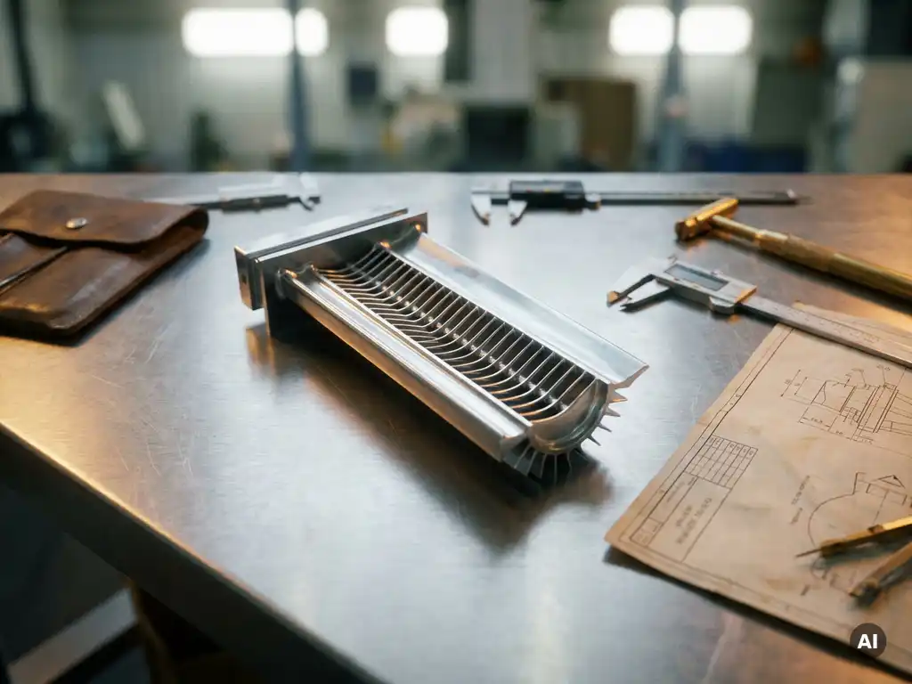
Design for manufacture should be considered from the very beginning of product development, ideally during the concept phase before any geometry or material choices are locked in. The earlier DFM principles are applied, the more freedom engineers have to shape a design around production realities rather than retrofitting manufacturability into a finished concept. The sections below address the most common questions about when, how, and by whom DFM decisions should be made.
What happens when DFM is applied too late in development?
When design for manufacture is applied too late, the cost and effort of making changes rises sharply. By the time a product reaches the prototype or pre-production stage, decisions about geometry, tolerances, and materials have already been made, and reworking them means revisiting engineering drawings, retesting components, and potentially scrapping tooling. Late-stage manufacturability problems are not just expensive, they delay product launches and erode confidence between engineering and production teams.
The underlying issue is that design decisions compound. A geometry chosen early for aerodynamic performance may require a machining process that is difficult to control at scale. A wall thickness that looks acceptable on a CAD model may be impossible to maintain consistently in casting. Each of these choices narrows the manufacturing options available downstream, and by the time production engineers review the design, their feedback often triggers a cycle of design revisions, re-analysis, and repeat testing.
In high-precision industries such as aerospace, the consequences are amplified. Components must meet tight dimensional and material specifications, and any deviation discovered late in development can require full requalification. The financial and schedule impact of a single late-stage DFM issue in an aero engine program can easily outweigh the cost of an entire early-stage design review.
At what stage of product development should DFM begin?
DFM should begin during the concept phase, before detailed geometry is defined. At this stage, engineers still have maximum flexibility to select manufacturing-friendly forms, materials, and joining methods. Waiting until detailed design or prototyping to consider manufacturability means working against decisions that are already partially fixed.
The concept phase is when the broadest trade-offs are made: what manufacturing process will be used, what material family is appropriate, what level of dimensional precision is genuinely required. These choices set the boundaries for everything that follows. If a component is conceived as a single machined part when it could be produced more efficiently as a casting with light finish machining, that realisation is far less disruptive at the concept stage than during detailed design.
That said, DFM is not a single event. It should be revisited at each development gate, with increasing specificity. At the concept stage, the focus is on process selection and general geometry. At detailed design, it shifts to tolerances, surface finishes, and feature accessibility for tooling. At the prototype stage, it becomes about validating that the design can be produced consistently and to specification across a production run, not just in a one-off build.
How does DFM differ across concept, detailed design, and prototype phases?
DFM takes a different form at each phase of development because the decisions available to engineers change as the design matures. At the concept stage, DFM is strategic, focused on process selection, material choices, and part count. At detailed design, it becomes analytical, examining specific features for machinability, casting feasibility, or assembly access. At the prototype phase, it is empirical, using physical builds to expose production risks that analysis alone did not catch.
Concept phase
During concept development, the primary DFM question is whether the chosen manufacturing route is appropriate for the component’s function, volume, and precision requirements. Engineers should evaluate whether a part can be simplified, whether multiple parts can be consolidated, and whether the proposed material is compatible with available production processes. These decisions have the highest leverage because they define the entire manufacturing approach.
Detailed design phase
At detailed design, DFM shifts to feature-level analysis. This includes reviewing tolerances to confirm they are achievable without exceptional process control, checking that internal features are accessible to cutting tools or inspection equipment, and confirming that surface finish requirements are consistent with the chosen process. Simulation tools such as finite element analysis and process modelling are commonly used at this stage to predict manufacturing outcomes before physical parts are made.
Prototype phase
Prototype builds serve as a practical DFM audit. They reveal where the design theory meets production reality: which tolerances are consistently achievable, where fixturing is difficult, and which assembly sequences create access problems. Findings from prototype builds should feed directly back into the design, and any changes made at this stage should be re-evaluated for their effect on the original functional requirements.
Which team members should be involved in DFM decisions?
DFM decisions should involve both design engineers and manufacturing engineers working together from the concept phase onward. Effective DFM requires the design team to understand production constraints, and the manufacturing team to understand functional requirements. When these groups work in isolation, the result is typically a design that performs well in analysis but creates significant problems on the shop floor.
Beyond these two core groups, the composition of a DFM review depends on the component and the production route. For machined components, tooling engineers and CNC programmers bring knowledge of what geometries are practical and where cycle times will spike. For cast or forged parts, foundry or forging specialists can identify draft angles, wall thickness limits, and parting line constraints that a design engineer may not anticipate. For assemblies, production planners and quality engineers should be involved to assess inspection access and assembly sequence feasibility.
Procurement teams also play a role, particularly when material availability or supplier capability constrains what can be specified. A material that is theoretically ideal may be available only from a single source, or may require processing that extends lead times significantly. These considerations belong in DFM discussions, not as afterthoughts during purchasing.
How does DFM apply to high-precision aerospace and turbine components?
For aerospace and gas turbine components, DFM applies with particular intensity because the gap between what is functionally required and what is practically manufacturable is often narrow. Turbine blades, compressor stages, and combustion hardware must meet strict aerodynamic, thermal, and structural specifications while being produced consistently across many units. Manufacturability cannot be treated as secondary to performance in these applications.
The specific DFM challenges in aerospace component development include managing tight geometric tolerances on complex three-dimensional surfaces, specifying surface finishes that are both functionally necessary and achievable with available processes, and selecting materials that can withstand operational temperatures while remaining processable through forging, casting, or additive manufacturing routes.
Testing plays a direct role in DFM for gas turbine hardware. Aerothermal testing of compressor and turbine components provides validation data that confirms whether a manufactured part performs as designed, and whether any manufacturing variation within tolerance has a measurable effect on performance. For gas turbine development programs, this kind of experimental validation is not optional, it is the mechanism by which design assumptions are confirmed or corrected before production commitments are made.
What tools and methods support DFM analysis during development?
DFM analysis is supported by a combination of simulation tools, structured review methods, and physical testing. The appropriate tools depend on the manufacturing process being evaluated and the stage of development. No single tool covers all DFM needs, and the most effective programs use several in combination.
Computer-aided manufacturing (CAM) software allows engineers to simulate machining operations on a 3D model before any metal is cut, identifying where tool access is restricted, where cycle times are excessive, or where the required tolerances exceed what the process can reliably deliver. Casting simulation tools perform a similar function for cast components, modelling solidification behaviour to predict shrinkage, porosity, and residual stress.
Finite element analysis (FEA) supports DFM indirectly by confirming that a design modified for manufacturability still meets its structural and thermal requirements. When a geometry is simplified to reduce machining complexity, FEA can verify that the change does not introduce stress concentrations or reduce thermal margins.
Structured review methods such as design for manufacture and assembly (DFMA) workshops bring together cross-functional teams to systematically evaluate a design against a defined set of manufacturability criteria. These sessions are most effective when they occur at defined development gates rather than as ad hoc reviews, and when they produce documented outputs that feed directly into design revisions.
Physical prototyping and component testing remain the most direct DFM validation method. Analysis can predict many manufacturing risks, but some only become apparent when a part is actually produced and measured. For components where performance is sensitive to manufacturing variation, experimental testing provides the empirical evidence that confirms the design is both manufacturable and functional.
How AneCom supports DFM validation for aero engine and turbine components
AneCom AeroTest provides the testing infrastructure and engineering expertise that makes DFM validation concrete for complex turbine and compressor hardware. Rather than relying solely on simulation to confirm that a manufactured component will perform as designed, development programs can use AneCom’s facilities to test physical hardware under controlled aerothermal conditions and generate the measurement data that closes the loop between design intent and manufacturing outcome.
- Aerothermal component testing for compressors, combustors, and turbine stages, producing validation data that confirms whether manufactured hardware meets its performance specification
- Fan system acoustic testing in Europe’s largest anechoic chamber, where noise performance of manufactured fan assemblies can be validated under controlled free-field conditions
- Instrumentation and assembly services that support the preparation of test hardware, including components built to DFM-modified designs that require verification before production commitment
- Non-destructive testing services that assess the integrity of manufactured components without causing damage, supporting quality assurance at the interface between design and production
If your development program has reached a stage where manufactured hardware needs experimental validation, contact AneCom AeroTest to discuss how the available test capabilities can support your DFM process.
Related Articles
- How many design concepts should engineers evaluate before selecting one?
- When should a mechanical concept be rejected?
- How do you interpret the results of a Pugh matrix?
- What is the difference between static and rotating component design?
- When should maintainability be considered during mechanical design?