Mechanical design changes fundamentally when a system rotates at high speed under heavy load. The combination of centrifugal force, cyclic stress, thermal gradients, and dynamic instability creates a set of structural demands that static components simply do not face. These demands shape every decision from material selection to geometry, and understanding them is essential for engineers working on aero engines, gas turbines, and related rotating machinery.
What forces make rotating systems mechanically demanding?
Highly loaded rotating systems are mechanically demanding because they experience centrifugal forces, gyroscopic effects, and cyclic bending loads simultaneously, all of which scale with rotational speed and component mass. Unlike static structures, every rotation introduces a complete stress cycle, meaning that even a steady operating condition generates fatigue loading at the material level.
Centrifugal force is the dominant structural driver in most rotating components. In a compressor or turbine disk, the outward pull on the blade roots and disk rim can reach tens of thousands of Newtons per blade, depending on tip speed and blade mass. This force creates radial tensile stress in the disk and bending stress at the blade attachment, both of which must be accounted for in the structural design.
Gyroscopic effects become relevant whenever the axis of rotation changes direction, as it does during aircraft maneuvers. These moments load bearings and shafts in ways that are absent during ground testing on a fixed rig, which is one reason that engine qualification testing must replicate flight load conditions rather than just steady-state operation. Aerodynamic pressure loads from the working fluid add a further layer of complexity, particularly in stages where pressure ratios are high and flow velocities are close to sonic.
How does fatigue life calculation differ in rotating components?
Fatigue life calculation in rotating components differs from static fatigue analysis because every revolution constitutes one stress cycle, meaning components accumulate fatigue damage continuously during operation. Engineers must account for both high-cycle fatigue from vibratory loads and low-cycle fatigue from start-stop cycles, and these two damage modes are tracked separately and then combined.
High-cycle fatigue arises from aerodynamic excitation at blade-passing frequencies and from rotor-stator interaction. A single engine flight hour can introduce millions of stress cycles at these frequencies, so the material must operate well below the endurance limit for the relevant stress amplitude. Low-cycle fatigue accumulates more slowly but with much larger stress amplitudes, driven by the centrifugal and thermal loads that build up during each engine start and dissipate during shutdown.
The interaction between these two fatigue modes is handled through a damage accumulation model, where the fraction of life consumed by each load type is summed. Mean stress corrections, surface finish factors, and stress concentration factors at features like blade fir-tree roots or cooling holes must all be applied. For aerospace rotating components, regulatory frameworks set hard limits on allowable fatigue consumption before mandatory inspection or replacement, which means the life calculation must be conservative and well validated against test data.
What materials are used in highly loaded rotating systems?
Highly loaded rotating systems use nickel-based superalloys for the hottest sections, titanium alloys for compressor stages operating at moderate temperatures, and high-strength steels for shafts and structural casings. Material selection is governed by the combination of temperature, stress level, and required fatigue life at each location in the engine.
Nickel superalloys retain useful strength at temperatures exceeding 1,000 degrees Celsius, which makes them the standard choice for high-pressure turbine blades and disks. Single-crystal casting eliminates grain boundaries in the blade’s radial direction, removing a common crack initiation site and extending creep life significantly. Thermal barrier coatings applied to blade surfaces allow metal temperatures to remain below the alloy’s capability limit even when gas temperatures exceed it.
Titanium alloys offer a favorable strength-to-weight ratio at the lower temperatures found in compressor stages, and their resistance to fatigue crack growth makes them well suited to the cyclic loading environment. However, titanium’s susceptibility to fretting at contact interfaces, such as blade-disk attachment features, requires careful surface treatment and geometry control. For fan blades in modern turbofan engines, carbon-fiber composites with metallic leading-edge protection have become common, offering mass savings that directly reduce centrifugal loads on the disk.
How does rotordynamic analysis shape the mechanical design?
Rotordynamic analysis shapes mechanical design by identifying the natural frequencies of the rotating assembly and ensuring that critical speeds do not coincide with operating speeds or excitation frequencies. When a rotor’s natural frequency aligns with an excitation source, resonance amplifies vibration amplitudes rapidly, leading to accelerated fatigue damage or catastrophic failure.
The analysis begins with a model of the shaft, disks, and blades as a coupled system, with bearings represented by their stiffness and damping characteristics. The model predicts critical speeds, which are the rotational speeds at which natural frequencies are excited by imbalance or aerodynamic forces. Designers then either shift these critical speeds away from the operating range by adjusting shaft stiffness or disk mass distribution, or they ensure that adequate damping is present to limit response amplitudes if a critical speed must be traversed during run-up.
Blade-disk interaction is a specific concern in turbomachinery. The blades themselves have natural frequencies that must avoid coinciding with the engine-order excitation lines on a Campbell diagram, which plots frequency against rotational speed. Mistuning, where small manufacturing variations cause each blade to have a slightly different natural frequency, can either amplify or reduce the response depending on the pattern, and this effect is now routinely incorporated into the design process for high-pressure turbine and compressor stages.
Why does thermal management become a structural design problem in rotating systems?
Thermal management becomes a structural design problem in rotating systems because temperature gradients across a component generate differential thermal expansion, which produces internal stress even without any mechanical load applied. In a turbine disk, the hot bore and cooler rim expand at different rates during transient conditions, creating thermal stresses that can exceed the mechanical stresses from centrifugal loading.
During engine acceleration, the rim of a turbine disk heats faster than the bore because it is directly exposed to hot gas. This creates a compressive stress at the rim and a tensile stress at the bore. During deceleration, the gradient reverses. Each thermal transient therefore adds a stress cycle to the component’s fatigue history, and the severity of this cycle depends on how quickly the engine accelerates and how effectively cooling air is distributed through the disk.
Cooling air routing in gas turbine rotors is itself a structural design problem. Holes, slots, and channels must be positioned to deliver cooling flow efficiently, but each feature introduces a stress concentration. The geometry of cooling passages in turbine blades is particularly constrained because the blade must carry centrifugal load while also conducting heat away from the metal surface. Computational thermal-structural analysis, validated against experimental measurements, is the standard method for resolving these competing requirements in gas turbine rotor design.
How is mechanical design validated for highly loaded rotating components?
Mechanical design for highly loaded rotating components is validated through a combination of component-level rig testing, full-assembly testing, and post-test inspection. Analytical predictions from finite element models and rotordynamic analyses are necessary but not sufficient on their own; physical testing under representative conditions is required to confirm that the design performs as calculated.
Component testing typically begins with spin pit tests, where a disk or bladed disk is accelerated to overspeed conditions in a containment vessel to verify burst margin and to check that stress distributions match predictions. Vibration testing under controlled excitation confirms natural frequencies and damping values. Thermal cycling tests replicate the low-cycle fatigue loading from repeated engine starts and shutdowns, generating data that validates the life prediction model.
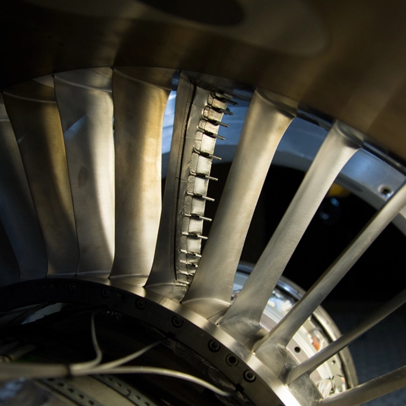
Full assembly testing in a compressor or turbine test facility provides the most representative validation environment. Instrumented test articles carry strain gauges, thermocouples, and pressure taps that record the actual loading experienced during operation, and these measurements are compared directly against design predictions. Discrepancies between measured and predicted values drive design corrections before the component enters service. Non-destructive inspection methods, including fluorescent penetrant inspection and ultrasonic testing, are applied before and after test campaigns to detect any crack initiation that may have occurred.
How AneCom AeroTest supports mechanical design validation for rotating systems
AneCom AeroTest provides experimental validation services specifically designed for the demands of highly loaded rotating components. Working from the Aerospace Technology Centre in Wildau, the company supports engineers at every stage of the mechanical design process, from instrumented compressor testing through to aeroacoustic validation in Europe’s largest anechoic chamber. Concrete capabilities include:
- Aerothermal component testing for multistage compressors and aero engine fans on dedicated test benches
- Instrumentation, assembly, and test execution for bladed disks, casings, and full compressor stages
- Acquisition of validation test data for fatigue life model calibration and rotordynamic verification
- Non-destructive testing services, including inspection before and after structural test campaigns
- Support for combustor and turbine component testing through established cooperation partner facilities
If you are developing or qualifying a rotating system and need experimental data to support your structural analysis, contact AneCom AeroTest to discuss your test requirements.