
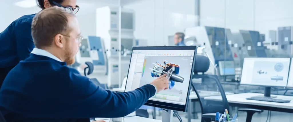
Rotating machinery is difficult to design because it must simultaneously manage extreme mechanical stress, thermal gradients, aerodynamic instability, and material limitations, all while spinning at thousands of revolutions per minute. Every design decision involves competing constraints, and a failure in any one area can compromise the entire system. The sections below address the specific engineering challenges that make this work so demanding.
What engineering forces make rotating components so hard to control?
Rotating components are difficult to control because they experience multiple force types at once: centrifugal loads, vibrational excitation, gyroscopic effects, and pressure differentials, all of which interact in ways that are hard to predict from static analysis alone. The challenge is not any single force but the way these forces combine and amplify each other under real operating conditions.
Centrifugal loading is the most immediately obvious problem. As a component spins, mass distributed away from the axis of rotation generates an outward force proportional to the square of rotational speed. A blade that weighs only a few hundred grams can exert forces equivalent to several tonnes on its attachment point at operating speed. This means even small geometric imperfections or mass imbalances create disproportionate stress concentrations.
Vibration adds another layer of difficulty. Rotating components pass through resonance frequencies during startup and shutdown, and sustained resonance at operating speed can cause fatigue failure far below the material’s ultimate strength. Engineers must map the natural frequencies of every component and ensure that operating speeds do not coincide with excitation frequencies from adjacent stages, inlet distortions, or structural supports. This process, known as Campbell diagram analysis, is fundamental to aerospace turbomachinery design but rarely produces clean solutions on the first attempt.
Why do thermal gradients cause such severe problems in rotating parts?
Thermal gradients cause severe problems in rotating parts because differential expansion between hot and cool regions generates internal stress that cannot be relieved by the component moving freely. In a static structure, thermal expansion is manageable. In a rotating component constrained by attachment points and adjacent geometry, the same expansion creates cyclic stress that accumulates into fatigue damage over thousands of operating hours.
Gas turbine components face temperature differences that can exceed several hundred degrees Celsius across a single blade. The leading edge, exposed directly to hot combustion gases, heats rapidly, while the root, embedded in a cooler disc, remains comparatively cold. This gradient creates a bending moment within the blade itself. Multiply this by millions of thermal cycles over a service life, and the cumulative fatigue damage becomes a primary design constraint.
Cooling strategies address this partially, but they introduce their own complications. Internal cooling channels reduce the effective cross-sectional area available to carry mechanical loads and create stress concentrations at channel walls. Film cooling, which bleeds air through surface holes to form a protective layer, alters the aerodynamic profile and affects stage efficiency. Every degree of temperature reduction comes at a performance cost that must be justified in the overall design balance.
What is the relationship between rotational speed and structural failure risk?
Structural failure risk increases with rotational speed at a rate that is not linear. Because centrifugal stress scales with the square of angular velocity, doubling the rotational speed quadruples the centrifugal load on rotating components. This relationship means that small increases in design speed, even those driven by efficiency targets, can push components into stress regimes that require fundamentally different materials or geometries.
The disc, which carries the blades, is particularly sensitive to speed. Disc burst, where a disc fractures under centrifugal load and releases fragments at high velocity, is one of the most catastrophic failure modes in turbomachinery. Certification requirements mandate that engines demonstrate containment capability, meaning the casing must be able to contain disc fragments if a burst occurs. Designing for containment while keeping casing weight acceptable is a significant engineering problem in its own right.
Creep is another speed-related failure mechanism. At elevated temperatures and sustained stress, metallic components deform slowly over time even when stress remains below the yield point. Higher rotational speeds increase the sustained stress, accelerating creep rates and reducing component life. Designers must predict creep deformation over thousands of hours and ensure that dimensional changes remain within tolerance throughout the intended service interval.
How does aerodynamic instability affect compressor and turbine design?
Aerodynamic instability affects compressor and turbine design by setting hard boundaries on the operating range of each stage. In compressors, the most significant instability is surge, a violent flow breakdown that occurs when the pressure rise demanded of the compressor exceeds what the blade geometry can sustain at a given flow rate. Surge causes rapid, cyclic reversal of flow through the machine and can cause structural damage within seconds.
Stall, which can precede surge, occurs when the angle of attack on individual blades exceeds the point at which attached flow can be maintained. A stall cell, a region of separated flow, can rotate around the annulus at a fraction of rotor speed, a phenomenon called rotating stall. This creates unsteady loading on blades and can excite resonant vibration, combining aerodynamic and structural failure risks in a single event.
Turbine stages face different instability concerns. Flutter, an aeroelastic phenomenon where blade vibration is sustained or amplified by the surrounding flow rather than damped, is a particular concern in low-pressure turbine stages with long, thin blades. Predicting flutter boundaries requires coupled aerodynamic and structural analysis, and the interaction between blade flexibility and unsteady flow is still an active area of research in gas turbine engineering.
Tip clearance between rotating blades and the surrounding casing also plays a direct role in aerodynamic stability. Larger clearances reduce efficiency and can worsen stall characteristics, while tighter clearances risk blade-tip rubs during transient operating conditions such as rapid acceleration or thermal expansion events. Managing this clearance across the full operating envelope is one of the more demanding geometric tolerancing problems in the field.
What materials are used in rotating machinery and why are they so difficult to work with?
Rotating machinery components are made primarily from nickel-based superalloys, titanium alloys, and, increasingly, ceramic matrix composites. Each material class is chosen because it maintains mechanical properties at temperatures where most metals would lose structural integrity, but each also presents significant manufacturing, inspection, and repair challenges that add cost and complexity throughout the component lifecycle.
Nickel-based superalloys
Nickel-based superalloys dominate high-pressure turbine applications because they retain strength and resist oxidation at temperatures approaching their own melting points. Many high-pressure turbine blades are cast as single crystals, eliminating the grain boundaries where creep and fatigue cracks preferentially initiate. Single-crystal casting is a tightly controlled process with significant scrap rates, and any deviation in solidification conditions can produce a component that must be rejected. Machining these alloys is also demanding because their hardness and work-hardening behaviour rapidly wear cutting tools.
Titanium alloys
Titanium alloys are used extensively in compressor stages and fan systems because they offer a high strength-to-weight ratio at moderate temperatures. The weight saving relative to steel is significant in rotating components, where mass directly translates to centrifugal load. However, titanium is susceptible to a phenomenon called titanium fire, where the material ignites in the presence of high-pressure air under certain conditions. This limits its use in the higher-temperature stages of a compressor and requires careful assessment of rubbing contact scenarios.
Ceramic matrix composites
Ceramic matrix composites are entering service in turbine components because they can withstand higher temperatures than metallic alloys while being significantly lighter. Their primary difficulty is brittleness. Unlike metals, which deform plastically before fracture and provide warning of impending failure, ceramic composites can fail suddenly under impact or thermal shock. Inspection methods developed for metallic components do not always transfer directly, and new non-destructive evaluation techniques are needed to assess the internal fibre architecture and detect damage.
How is rotating machinery tested to validate its design before certification?
Rotating machinery is validated through a structured sequence of tests that progress from component-level experiments to full engine certification runs. Testing at each stage is designed to confirm specific design assumptions, identify failure modes before they occur in service, and generate the empirical data needed to satisfy airworthiness authorities. No computational model, however sophisticated, substitutes for this physical validation process.
Component testing comes first. Individual compressor stages, fan systems, and turbine assemblies are tested in dedicated rigs that replicate the aerodynamic and mechanical conditions of engine operation without requiring a complete engine. This allows engineers to measure performance maps, identify instability boundaries, and validate structural predictions at a fraction of the cost and complexity of full-engine testing. Instrumentation at this stage is typically far more extensive than anything possible in a production engine, with hundreds of pressure taps, temperature sensors, and strain gauges providing a detailed picture of component behaviour.
Acoustic testing is a distinct validation activity for fan systems. Engine noise is a regulated parameter, and fan design must demonstrate compliance with certification limits before an aircraft can enter service. Anechoic test facilities suppress reflections from surrounding walls, creating free-field acoustic conditions that replicate the environment around an aircraft on an airfield. This allows accurate measurement of fan noise characteristics without the interference of test cell reflections, giving designers reliable data to compare against certification thresholds.
Full engine testing follows component validation and covers performance, durability, and safety cases including blade-off events and ingestion of foreign objects. Certification testing is governed by detailed regulatory requirements and must demonstrate margins above normal operating conditions. The data generated feeds back into design refinement, and it is common for testing to identify behaviour that was not fully captured by analysis, requiring further design iteration before certification is achieved.
How AneCom AeroTest supports rotating machinery validation
AneCom AeroTest provides independent testing and engineering services specifically for the aerothermal components at the heart of rotating machinery design. For development programmes where test data quality and facility independence matter, AneCom offers:
- Multistage compressor and fan testing at the Compressor Test Center in Wildau, with instrumentation, assembly, and test execution managed from a single source
- Acoustic fan validation in Europe’s largest anechoic chamber, with a 1,000 m² footprint and wall reflection below 1% from 200 Hz to 40 kHz, providing free-field conditions for certification-relevant noise measurements
- Combustor and turbine test services through established cooperation partner facilities
- Non-destructive testing and support for turbine blade inspection and qualified repair
- Engineering services covering design, analysis, and instrumentation at customer sites worldwide
If your programme requires validated test data for compressor stages, fan acoustics, or aerothermal components, contact AneCom AeroTest to discuss how independent testing can support your development and certification timeline.
Ähnliche Artikel
- What should engineers consider when designing rotating components?
- What is detailed design in mechanical engineering?
- When should Design for Manufacture be considered during product development?
- How do engineers evaluate technical risk when selecting a design concept?
- When should maintainability be considered during mechanical design?