Compressor Test
What is a compressor test?
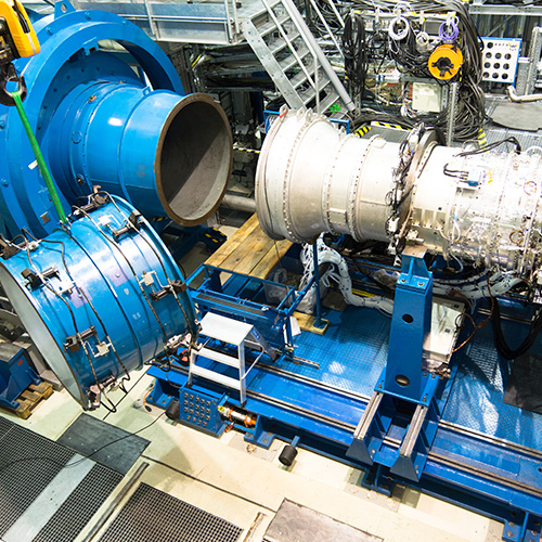
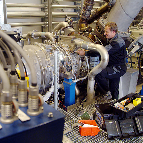
- Test compressor component for aircraft engines or industrial gas turbines as part of a development programme
- Establish complete compressor map and operating characteristics of a compressor, including determination of the operating limits (surge line, choke line)
- High resolution measurement technology used to identify stage-by-stage performance
- Provide first data in a development programme for mechanical integrity of compressor blading
- Establish and optimise bleed and VGV schedules
- Provide data base for improvement of the numerical algorithm

Keyfacts
- Electric drive system providing up to 18,000 kW (24,000 HP)
- 11 controllable pipe measuring sections for bleed air extraction
- Control of up to 5 (extendable to 7) variable guide vane stages driven by hydraulic jacks
- Versatile rig oil system for roller/ball or journal bearings
- Secondary air supply system, e.g. for buffer seal air or instrumentation cooling
- Versatile and programmable compressor & facility control system with built-in safety concept
- Various gear sets, speeds of up to 15,200 RPM
- Split flow test facility with maximum mass flow of 200 kg/s at the inlet, 150 kg/s at the bypass and 65 kg/s at the core
- Reduction of inlet pressure down to 0.2 bar
- Maximum compressor outlet conditions of T=460 °C and P=11.0 bar in the bypass section (or as single flow)
- Axial thrust piston to compensate maximum axial force of 80 kN
- Various gear sets, speeds of up to 24.000 RPM
- Primary single flow test facility with maximum mass flow of 50 kg/s (extension to split flow possible)
- Reduction of inlet pressure down to 0.2 bar
- Maximum compressor outlet conditions of T=640 °C and P=21.4 bar
- Inlet air can be heated up by up to 100 °C above ambient
Measurement system capabilities
- Ambient pressure, temperature and relative humidity at the facility inlet
- Pressure in the inlet Venturi
- Temperature at several points in the test facilities including the anechoic chamber
- Mass flow in the inlet Venturi/ flare (HP, IP and Anechoic), in the bleed lines (HP and IP) and in the core exhaust lines in the IP and Anechoic testbed
- Speed and torque at the drive shaft
- Compressor thrust compensation force of the balance piston (part of the torquemeter) – IP and Anechoic testbeds only
- Oil and air supply parameter for the compressor bearings
- Valve positions
- Health & safety measurements on all systems (vibrations, temperatures, pressures,etc.)
- Pressure:
- 1418 HP & IP test facility
- 1184 Noise test facility
- Temperature:
- 480 thermocouple (type E, J,K,N,T) HP & IP facility
- 300 thermocouple (type E, J,K,N,T) Noise test facility
- 32 RTD channels - Analogue voltages: >150
- Frequency inputs: 16
- Vibration channels:
- 20 HP & IP test facility
- 26 Noise test facility - DC strain: 8
- Various:
- Tip timing on Noise test facility
- Tip clearance measurement on HP & IP test facilty
- 384 channels @ 250 kHz maximum sampling rate (configurable), fully synchronized
- Used for high frequency inputs, e.g.
- vibration measurements (strain gauges)
- noise measurements
- fast pressure transducers - Real-time monitoring and limit checking of all input channels at a time
- Monitoring of up to 32 modal limits per channel
- Real-time displays, including Campbell, Z-Mod, Oscilloscopes, FFT
